Table of Contents
Basic operation
To function, the Rhythm Sequencer needs to be driven by a V/Bar signal.
The setup below shows a Song Control and a Song Part module configured to create a basic Song Control Sequencer that feeds a V/Bar signal to the Rhythm Sequencer.
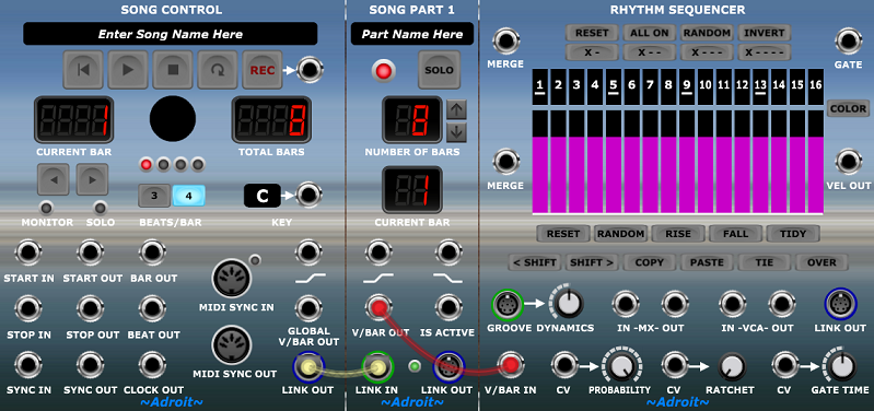
Pressing the Play button on the Song Control module will make the Rhythm Sequencer run for 8 bars and then stop. Engage the Loop button on the Song Control module to make the Rhythm Sequencer play continuously.
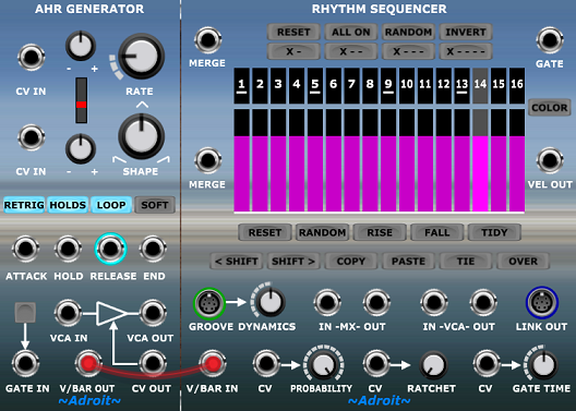
An alternative is to use the V/BAR OUT from an AHR Generator either to create a one off triggered sequence or a free-running repeating sequence if the generator’s LOOP button is engaged…
Normally the Rhythm Sequencer cycles at a rate of one complete sequence per bar. However, this relationship can be changed by manipulating the V/Bar signal with a Time Flow Changer module.
To illustrate the operation of the Rhythm Sequencer a CV Watcher module can be wired up as follows…
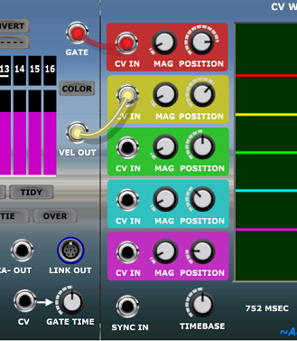
The TIMEBASE control on CV Watcher can be adjusted to zoom in and out on the traces.
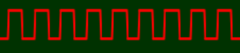
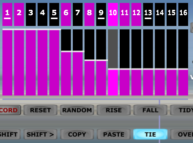
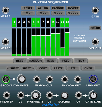
By default the sequencer’s numbered gate buttons are all off. To switch them all on either click on the ALL ON button or left click on button 1 and swipe the mouse all the way to button 16 while keeping the mouse button pressed.

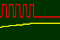
The gate output will then become a steady stream of pulses as shown by the upper trace on the CV Watcher module.
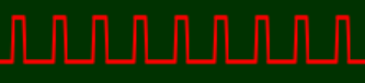
The length of these gate pulses can be adjusted by the GATE TIME knob or by a control voltage fed to the CV IN socket to the left of the knob.

The CV Watcher trace above shows the default 50% gate setting, while the trace below shows the gate pulses when GATE TIME is set to 25%.
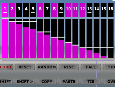
A click on the upper RANDOM button will switch the gate buttons to a random pattern such as the following…

This pattern produces the following stream of gate pulses…

Note that each step that is on produces its own individual pulse.
Now engage the TIE button.

Now adjacent gate buttons that are switched on produce a single sustained pulse – the steps are tied together.

The Rhythm Sequencer’s gate output might typically be used to control an envelope generator (perhaps an AHR Generator) or MIDI note generators such as Chord Player or MIDI Drum Kit, but it’s just a standard 5 V gate signal so can be connected to any module that responds to gates or triggers. It could for instance be used to advance a clock-based step sequencer.
Velocity editing
The VEL OUT socket is primarily intended to produce velocity signals so that individual notes can have controllable accents, but the signal is simply a 0 to 5 V voltage that can be used for any purpose.
For example patching the VEL OUT socket to the CV IN socket next to the GATE TIME knob enables the velocity settings to control the gate length of each step, as illustrated below…

The relationship between velocity control settings and the VEL OUT signal is not entirely straightforward as the settings of the gate buttons and the TIE button change the way in which velocity is handled.
There are three rules that determine whether an individual step’s velocity control affects the VEL OUT signal:
- When a step’s gate is off the velocity control is ignored.
- When a step is tied to a previous step the velocity control is ignored.
- When a step is collapsed by Groove the velocity control is ignored.
This produces entirely desirable and consistent results but introduces some subtle complexity to the user interface.
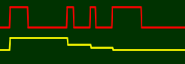
To illustrate this click on the FALL button to program the velocity controls into a downward sloping pattern. With the previously used random gate pattern and with the TIE button still engaged the Rhythm Sequencer should look something like this…

The horizontal white lines on the velocity controls show the actual VEL OUT signal’s value after applying the rules above.
What’s going on here is that the velocity settings are being sampled and held each time a new note begins.
This can be seen on the CV Watcher traces…
If we switch TIE off then we will see a change as Rule 2 is no longer being applied.
This is reflected in the more complex CV Watcher traces…

For completeness, let’s look at the situation when every step’s gate is on and TIE is off…

Note that now each step has independent control of the velocity as neither Rule 1 nor Rule 2 apply.
And this is reflected in the CV Watcher traces, as expected…

The difference between the velocity controls and the actual VEL OUT signal shown by the white lines when the rules are applied can seem a little confusing at first.
Indeed an earlier design attempted to mask this difference but it introduced behaviour that was even more confusing.
So for those of us who like things to be as simple and as tidy as possible there is a TIDY button. This adjusts the velocity controls to match the actual velocities used according to the rules. This has no impact on the Rhythm Sequencer’s outputs, as only those velocity controls that are being ignored according to the rules are affected.
In effect it simply makes the user interface look tidier (although if the gate pattern is changed it will of course have slightly different results than if the velocity controls had been left alone).

When a Rhythm Sequencer is connected to a Groove module then the timing of steps can be manipulated up to the point where steps can occupy zero duration. This is called “Step Collapse” and when this happens such steps become transparent in Rhythm Sequencer to show that they no longer have any impact on velocity, gate signals or ties.

See the Groove module documentation for more information.
Chaining Rhythm Sequencers
Rhythm Sequencers can be chained together to form sequences of just about any length required.
There are two elements to this. Combining the output signals and generating V/Bar signals that pass control from one sequencer to another.
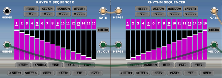
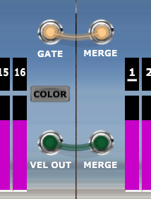
The former is relatively simple as all it involves is connecting all the sequencers together in a chain where the GATE OUT of a sequencer is connected to the upper MERGE socket of the next sequencer in the chain and the VEL OUT socket is connected to the lower MERGE socket.
The chain order would normally be the order of play in a simple setup (just to simplify the wiring, if nothing else) but this is not critical. Complex setups where there are multiple chains, for instance verse/chorus structures that repeat can still be accommodated.
How this works is that inactive Rhythm Sequencers simply pass the voltage at their MERGE inputs to their outputs. So providing that only one sequencer in a chain is active at a time the result is that the entire chain’s output is merged together and available via the GATE OUT and VEL OUT sockets of the final sequencer in the chain.
The other element – distributing control via V/Bar signals is slightly more complicated but once the principles are understood then simple setups are straightforward to create. There are also creative possibilities as a simple linear setup is just one option.
Let’s begin with a simple setup with two Rhythm Sequencers chained together.

Here the Time Split 2 module splits the V/Bar signal so that odd numbered bars drive the Rhythm Sequencer on the left and even numbered bars drive the Rhythm Sequencer on the right.
This time splitting technique can be extended to larger chains by using other time splitters such as Time Split 4, Time Split 8 and Time Split 16.
Time splitters such as Time Split Fills, Time Split Binary. Time Split Build and Time Split Break provide more options.
Another way to split time is to use Song Part modules (which are effectively special types of time splitter).
The following patch chains two Rhythm Sequencers together but uses Song Part modules instead of Time Split 2…

Note that the NUMBER OF BARS settings for the Song Part modules have been set at 1 bar. So the V/Bar signals produced by the two Song Part modules are identical to the outputs of the Time Split 2 module.
Any number of Song Part modules can be linked together and their NUMBER OF BARS settings can be anything from 1 to 64 bars so there is considerable flexibility here.
But time splitting isn’t limited to a flat system. Hierarchical structures of some complexity can be constructed.
To illustrate this let’s look at a patch that uses two levels of hierarchy. The upper one using two Song Part modules and the lower one using a Time Split 2 module and a Time Split Fill module…
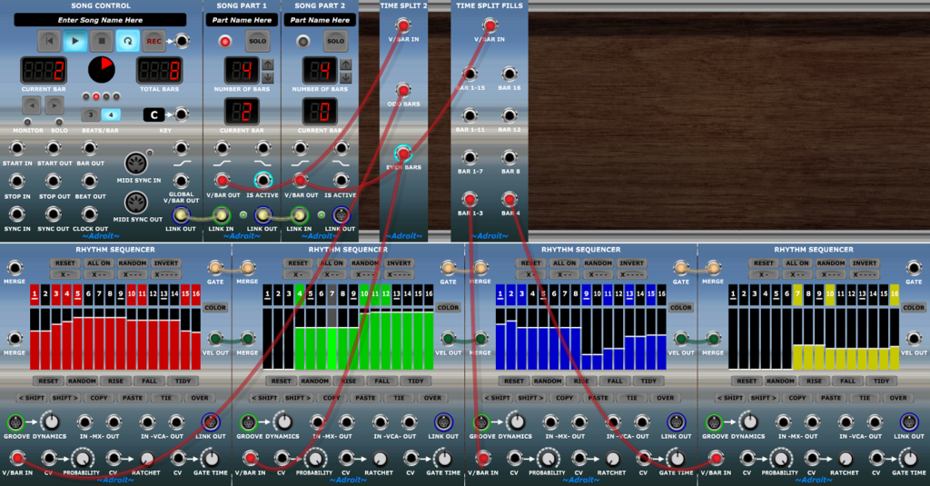
The Rhythm Sequencers have been color coded here (using their COLOR buttons) and this patch plays the sequencers in the following eight bar long pattern:
Red, Green, Red, Green, Blue, Blue, Blue, Yellow.
With several layers of hierarchy and the odd voltage controlled switch and/or Time Flow Changer module thrown in things can get really interesting for people wanting to explore complex generative patches.
Note that if you wish to use the built-in VCA facility when using chains of Rhythm Sequencers then you should use the VCA in the final sequencer in the chain as only this one will receive all of the velocity information.
Mutual exclusion
In some circumstances, for instance in programming hi-hat patterns, one wants to ensure that two Rhythm Sequencers do not have a gate on at the same step.
This can be automatically enforced by patching the MX OUT of each sequencer to the MX IN socket of the other as shown below.
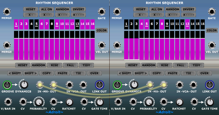
When wired together like this, setting a step’s gate on in one sequencer automatically switches off that step’s gate in the other sequencer.
Three beats per bar operation
To support 3/4 and related time signatures Song Control provides an option to switch from 4 beats per bar to 3 beats per bar.

This has serious consequences for a 16 step sequencer because 16 is not a multiple of 3.
Therefore when Song Control is set to 3 beats per bar the number of steps available in Rhythm Sequencer automatically adjusts to 12 – which is a multiple of 3.
This means that one beat corresponds to four Rhythm Sequencer steps whether working in 3/4 or 4/4 related time signatures.
When using the Groove module this may not actually be the case as Groove enables the timing of steps to be radically altered – to the point where steps can be “collapsed” (i.e. made to disappear). This allows you to create rhythms that use things like triplets and unconventional time signatures.
As it’s not often that 3/4 time is used in most modular synthesizer genres a little text message saying “12 STEPS WHEN 3 BEATS/BAR” pops up just to confirm what’s happening. It may be that you have selected three beats per bar accidentally.
Should you end up in a situation when building a new patch where Rhythm Sequencer is “stuck” in 3 beats per bar mode and you do not wish to use Song Control in the patch, then load up Song Control anyway, click on its 4 BEATS/BAR button then remove it from the patch.
Velocity end state
One consideration is what happens to the VEL OUT signal when a Rhythm Sequencer stops (i.e. when its V/BAR IN voltage drops to zero).
As a consequence of the way that chaining works a Rhythm Sequencer passes the voltages at its MERGE inputs to its outputs when it stops. This means that under normal circumstances both outputs fall to zero volts when a single Rhythm Sequencer stops or when an entire chain of Rhythm Sequencers stops, perhaps at the end of a song.

GATE OUT dropping to zero is of course what one wants but VEL OUT dropping to zero can be problematic. If the output is feeding a MIDI generator such as Chord Player or MIDI Drum Kit this is not an issue as the velocity is encoded at the beginning of the note, but in a situation where the velocity is controlling either the built-in or an external VCA the drop to zero might cause an abrupt ending to the final note.
But there is an easy way to fix this problem.
When using a single Rhythm Sequencer rather than a chain one can simply patch the VEL OUT socket back to the lower MERGE socket of the sequencer.

As the MERGE input is now the same voltage as VEL OUT the velocity voltage for the last step of the sequence is sustained as required…
This neat little trick also works when multiple Rhythm Sequencers are chained together too but it is important that only the VEL OUT of the final sequencer in the chain is connected to the lower MERGE socket of the first sequencer in the chain.