N-Step is a sophisticated extendable step sequencer designed for live performance and generative music applications.
- Five output channels, one dedicated to gate/trigger signals and four that provide control voltages suitable for controlling things like pitch.
- An extendable architecture that supports sequence lengths up to 128 steps or more.
- Innovative generative operations for manipulating sequencing data.
- Easy to use copy and paste facilities for constructing musical forms like AAAB or ABAC.
- Flexible support for chord progressions.
- Built-in quantization, sample and hold and glide.
- End of cycle and per-step trigger outputs.
- External CV control over dozens of parameters.
Table of Contents
Introduction
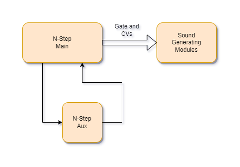
In order to be extendable an N-Step sequencer is constructed using two module types – N-Step Main and N-Step Aux.
The N-Step bundle also includes three ancillary modules from the Adroit LSSP system that help with pitch control (including the ability to create chord progressions) and a helper module called N-Step Remote.
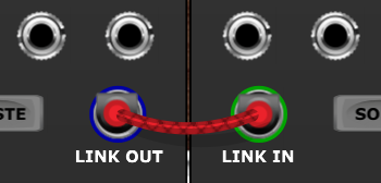
The minimum setup is one Main module and one Aux (auxiliary) module, this configuration supports up to 8 steps. Connections are made by patching the LINK OUT of the Main module to the LINK IN of the Aux module and the LINK OUT of the Aux module back to the LINK IN of the Main module in order to form a loop.
Any number of additional Aux modules can be inserted into the loop, each one adding support for another 8 steps. Each additional Aux module requires one extra cable.
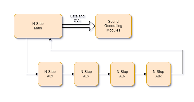
Sequence length is not restricted to multiples of eight steps. For instance if you want a sequence that is 10 steps long then you can achieve this by patching a cable from the 11th trigger Aux output to the Main module’s RESET input.
The sequence will then restart as soon as the 10th step has completed.
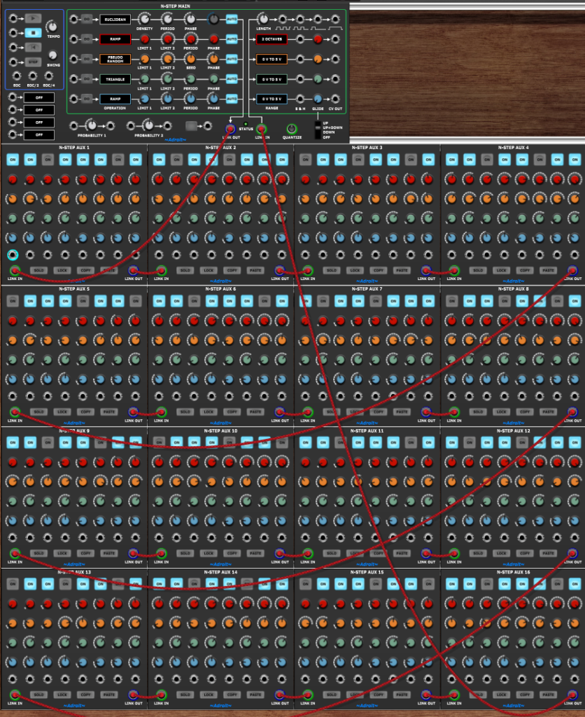
Although you might be tempted to build sequencers with extremely large numbers of steps, in practice you will find that 16 linked Aux modules (giving you a maximum of 128 steps) is probably the most you will ever want.
To support live perfomance all of the major controls are slightly over-sized and well spaced out to make it easier to operate the sequencer with either a touch screen or relatively broad-stroke mouse movements. Each Aux module also has a LOCK button that helps reduce the possibility of accidental changes.
To help with editing, Aux module also have SOLO, COPY and PASTE functions.

The bulk of the user interface consists of five rows of controls. In the Aux modules the upper row consists of on/off buttons that drive a gate/trigger channel. Below there are four rows of knobs that drive four control voltage channels.
These five Aux rows are reflected in the Main module. Here, as well as transport and configuration controls and interface connections, you will find all manner of interesting generative features built around the concept of performing operations on the individual channels. These operations can be triggered by manual button presses, knob tweaks, trigger inputs or changes in the values of CV inputs.
The control voltage channel outputs may be unquantized, quantized or use something called dynamic tuning. Sample and hold and glide functionality are also built-in.
Quick start guide
To get a feel for how N-Step works let’s load up a pretty basic patch…
After loading the patch into Voltage Modular you should be able to hear a simple sequence playing.
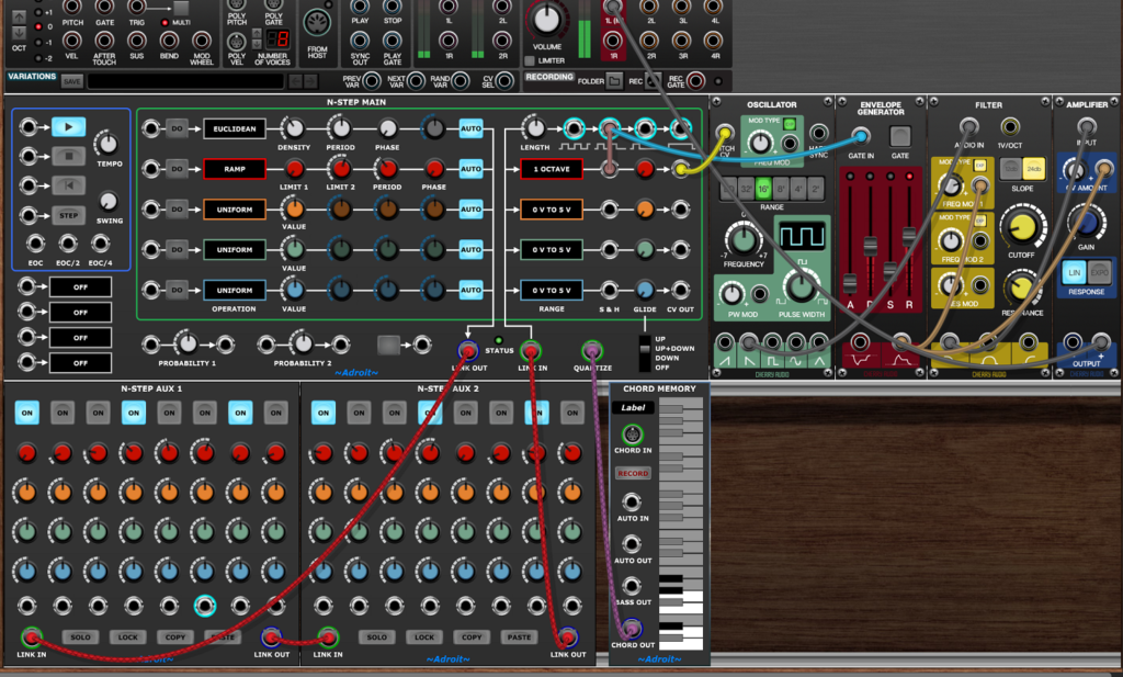
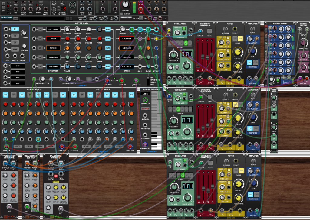
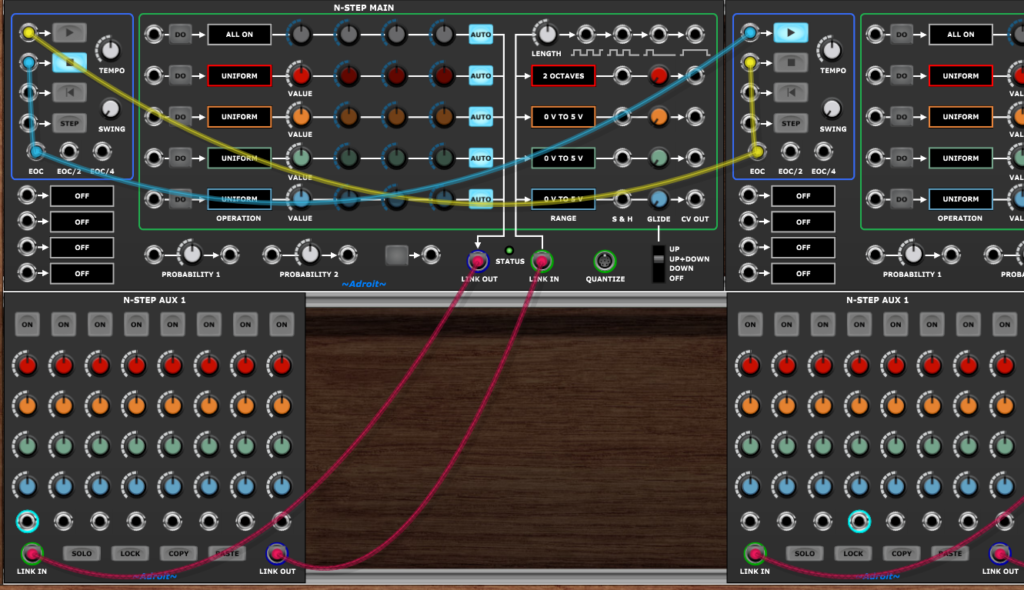
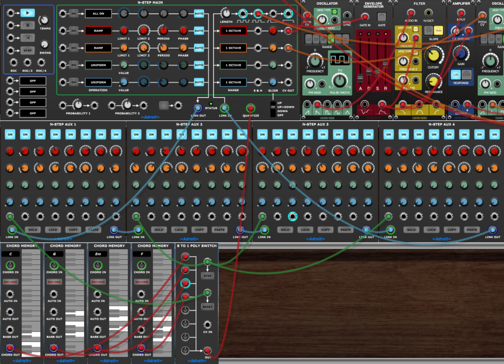
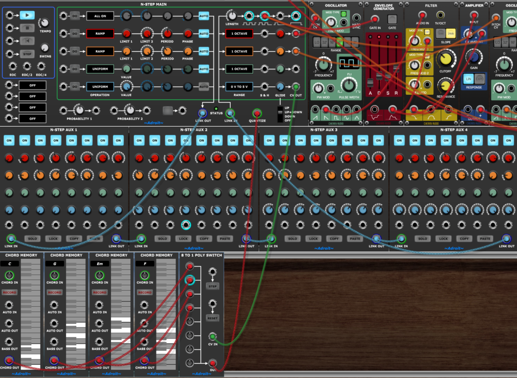
In the top cabinet we have an N-Step Main module on the left then on the right four modules from Cherry Audio’s free Nucleus package forming a primitive monosynth. This produces a very basic sound but it serves the purposes of this quick start guide.
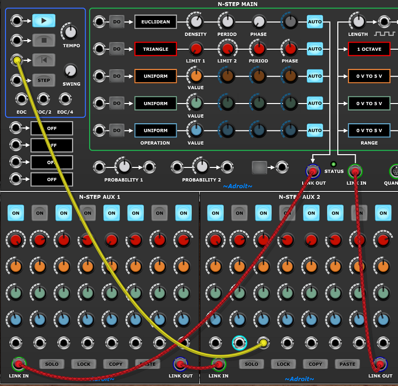
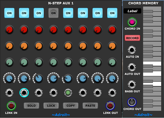
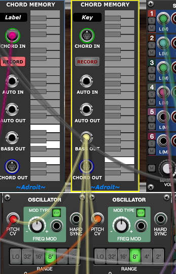
In the cabinet below there are two N-Step Aux modules giving us 16 steps to play with and a Chord Memory module that’s supplying a C natural minor scale to quantize the CVs so that we end up with something reasonably coherent rather than just a jumble of different pitches.
The Chord Memory module is borrowed from LSSP and will probably look different to the screenshot above when you first load it. Right click on the ~Adroit~ logo at the bottom of the module to change it to a plain dark background. This only needs to be done once.
In the lower cabinet you can click on any of the 16 ON buttons to change the rhythm and adjust the 16 red knobs to change the pitch sequence.
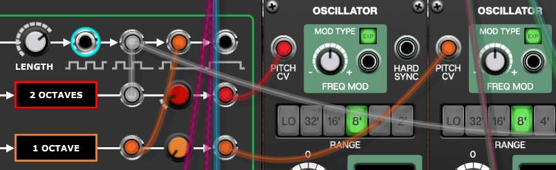
You’ll notice that the red knobs only have an impact on the pitch if the corresponding ON button is engaged. This is because the mauve colored cable at the top-right of the Main module is telling the red channel to use sample and hold to freeze the pitch when the corresponding ON button is disengaged.
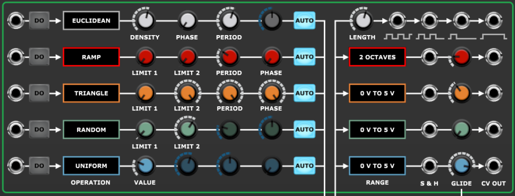
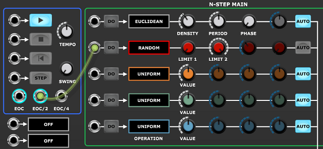
So far we’ve been in conventional sequencing territory but N-Step’s secret weapon is the ability to perform operations on channels. So locate the white DENSITY knob at the top of the Main module and slowly turn it up and down.
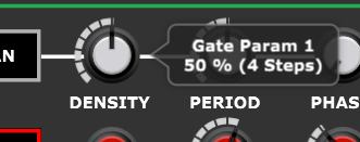
Now because the gate channel’s AUTO button is engaged, any change in the setting of the DENSITY parameter knob causes the gate channel’s currently selected operation to be executed automatically.

The currently selected gate channel operation is EUCLIDEAN and the PERIOD parameter is set at 8, so the DENSITY knob controls how many steps are on over an 8 step period using the Euclidean rhythm algorithm – which spaces out ON steps as evenly as possible.
DENSITY can be varied from 0% – resulting in silence, all the way up to 100% – where all steps are on.
The PHASE knob moves the pattern earlier or later in time. If you think of the pattern as being a “ring” consisting of PERIOD steps then PHASE effectively “rotates” it.
Note that the DENSITY and PHASE settings are percentages of the PERIOD rather than absolute values. So if a tooltip indicates that the DENSITY is “50% (4 steps)” be aware that the number of steps in parenthesis is just a helpful comment and could change if PERIOD changes.
Next let’s look at operations on the red CV channel which in this patch is controlling pitch.
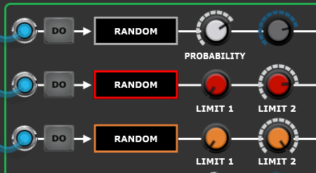
You may have been playing around with the red knobs of the Aux modules so to reinstate them to match the current operation settings click on the DO button of the red channel on the Main module. This forces the operation to execute and the red knobs of the Aux modules will return to their original values.
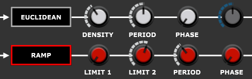
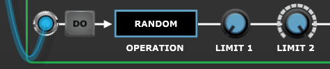
The Quick Start Patch settings for the red CV channel are shown below…

If you hover the mouse over the operation parameter knobs you’ll see that LIMIT 1 is set to the pitch C2 and LIMIT 2 is set to G2, PERIOD is set to 6 steps and PHASE is set to 0% (0 STEPS). As the selected operation is RAMP executing the operation sets the Aux module knobs in a repeating 6 step pattern that varies linearly between C2 and G2.
If you hover the mouse over the red knobs of the left-hand Aux module you will see that the first knob is set to the pitch C2 and the next five knobs are set at C#2, D#2, E2, F2 and finally G2. So the RAMP operation is automatically adjusting the knobs from LIMIT 1 (C2) to LIMIT 2 (G2) in 6 steps.
However, because a C natural minor scale is plugged into the QUANTIZE socket the actual pitches we hear are slightly different as they are adjusted to fit the scale.

After quantization the pitches end up being C2, D2, Eb2, F2, F2, G2.
So remember that the pitches that the tooltips show you are always the chromatic pitch before final quantization. In principle it would be possible to show fully quantized pitches but as we will see later the quantization becomes dynamic once we add chord progressions to the sequencing so N-Step just shows you the raw values rather than trying to predict the future.
Also note that only those pitches that correspond with a gate step that is ON are propagated because of the sample and hold function.
This all sounds more complicated than it really is. In effect N-Step is just doing tasks that are second nature to a musician skilled in improvisation who wants to translate relatively simple ideas into musically useful outcomes. In this instance the goal is to combine an 8 step rhythmical pattern with a 6 step rising pitch cycle ranging from C2 to G2 in C minor.
N-Step has a lot more tricks up its sleeve but it’s worth spending a while doing nothing more than exploring the interactions between the settings of the EUCLIDEAN gate and RAMP pitch operations.
There are seven parameters involved so there’s a fairly large search space but you might be surprised by how many familiar motifs you can unearth.
So far the gate signal has been coming from the second from left gate/trigger output and the sample and hold has been driven by the same signal, but there are actualy 12 different ways of usefully wiring up these two connections. The gate cable can be plugged into any of the four outputs and the sample and hold can either be omitted or be wired to the second or third output.
You can feed the sample and hold from the left-most or right-most gate/trigger outputs but these connections have the same effect as either not connecting the cable at all or connecting it to the third output respectively.
Depending on the exact ON button pattern and the settings of the red CV channel knobs wiring things up in these 12 different ways can result in 12 slightly different outcomes.
Try experimenting with different wiring to get an idea of the differences.
In addition we have two Bernoulli gates that can be used to introduce an element of chance into whether an envelope gate passes or whether the sample and hold makes a pitch change or freeze.
If that’s not enough, each step has its own trigger output on the Aux modules.
So it can get quite complicated if you desire.
All these combinations become very useful when using N-Step to drive multiple voices. Each voice can have independent pitch control and slightly different timing characteristics depending on exactly how you wire up the gates and the sample and hold.
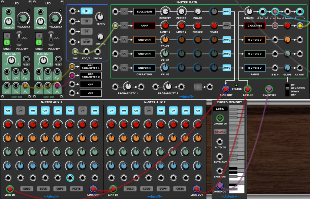
To illustrate how you might expand on the basic quick start patch here’s something that sounds a little more interesting…
This builds on the original patch by adding two more voices (using the same simple monosynth setup) and a little bit of drum programming using the individual step trigger outputs. Unlike the first patch this requires the Voltage Modular Core and Electro Drum modules to be installed.
It’s demonstrating all the techniques mentioned above but in just a single bar loop so it sounds pretty manic! You probably wouldn’t normally cram so much activity into such a short sequence.
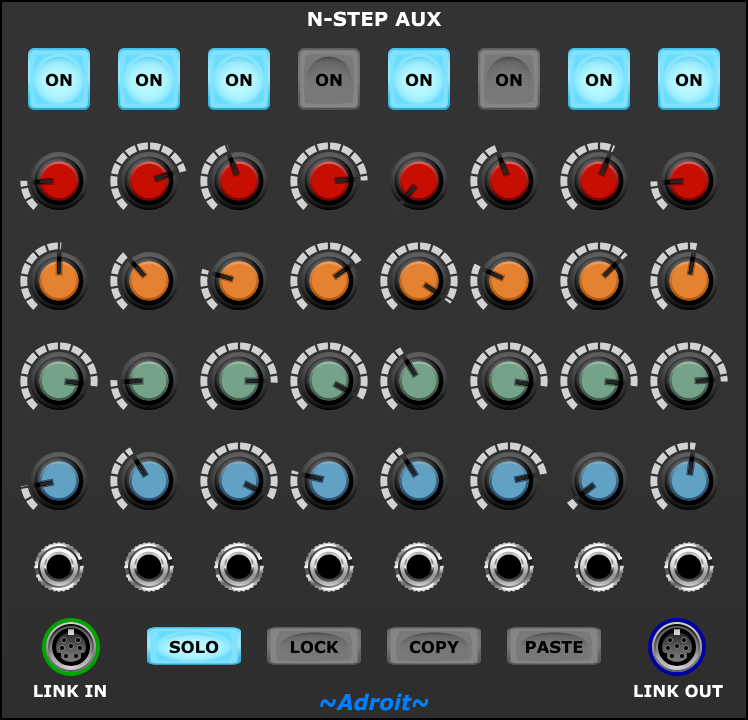
N-Step Aux module
An Aux module features 8 identical columns each representing a step.

An ON button – to set the gate/trigger pattern.
Red, orange, green and blue knobs to set four channels of CV. How the knob settings are interpreted is configured by each channel’s RANGE setting on the Main modue.
A trigger out socket that produces a brief 5 V pulse when the step becomes active.
An LED ring around the trigger out socket that illuminates to indicate that the step is active.
In addition at the bottom of the module…
A SOLO button – when enaged this disables and bypasses any other Aux modules in the loop so that you can focus on just one part of a sequence. Also any operations sent from the Main module only apply to the soloed Aux module.
A LOCK button – when enaged the Aux module is protected from accidental changes. Also when locked an Aux module ignores any operation sent from the Main module.
A COPY button – copies the ON button and knob settings to a clipboard. This enables all the data from one Aux module to be copied to another. This is extremely useful as it makes it easy to construct musical forms such as AAAB or ABAC where some phrases are repeated.
A PASTE button – pastes the ON button and knob settings from the clipboard.
LINK IN and LINK OUT sockets are used to create a loop from the Main module through however many Aux modules are required and then back to the Main module.
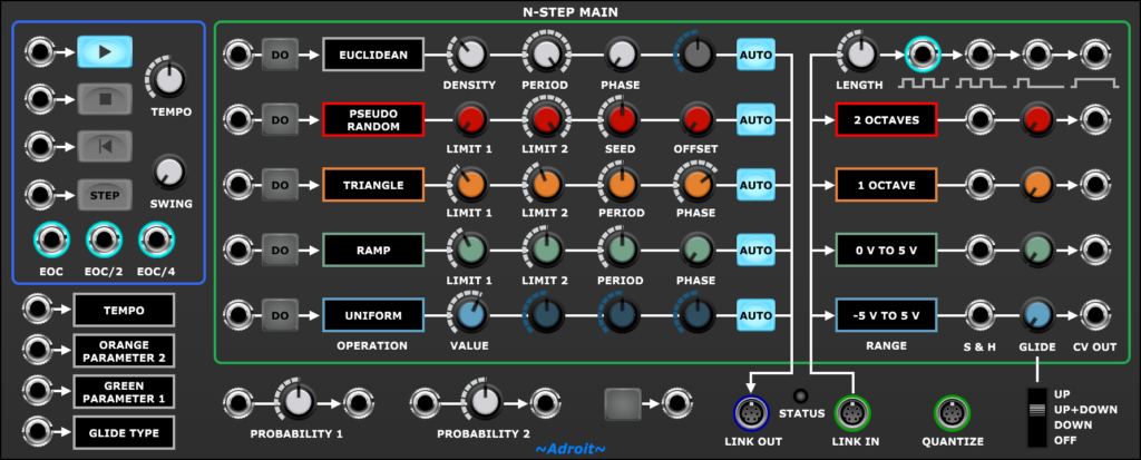
N-Step Main module
At first glance the N-Step Main module might look slightly intimidating as it includes a lot of controls for use in advanced applications, however basic sequencing is pretty straightforward. Anyone familiar with other step sequencers should feel at home after following the quick start guide.
Two sockets at the bottom of the Main module labelled LINK OUT and LINK IN are used to build a looped connection through one or more Aux modules and back.
The Main module’s LINK OUT socket should be connected to the LINK IN socket of the first (or only) Aux module in the loop. The LINK OUT socket of the last (or only) Aux module in the loop should be connected to the Main module’s LINK IN socket.
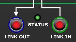
If the linkage connections are not wired up correctly then the STATUS LED flashes red.
The section of the Main module outlined in green reflects the same five sequencing channels as the Aux modules.
At the top is the gate/trigger channel with the four CV channels below (using the same red, orange, green, blue color-coding as the Aux modules).

The Gate/Trigger channel has (from left to right)…
An operation trigger input socket.
A DO operation button.
An OPERATION selector that when left clicked pops up a menu of options. Note that just selecting a new operation does not trigger it.
Four parameter knobs that change assignments depending on the type of operation selected.
An AUTO button. When this button is engaged any changes to the setting of a parameter knob automatically triggers execution of the currently selected operation, otherwise an operation only occurs when the DO button is pressed or a trigger is received via the trigger in socket.
A LENGTH knob.
Four different types of gate/trigger outputs.
The LENGTH knob and gate/trigger outputs are discussed in detail later.

The lower four channels output control voltages and have…
An operation trigger input socket.
A DO operation button.
An OPERATION selector that when left clicked pops up a menu of options. Note that just selecting a new operation does not trigger it.
Four parameter knobs that change assignments depending on the type of operation selected.
An AUTO button. When this button is engaged any changes to the setting of a parameter knob automatically triggers execution of the currently selected operation, otherwise an operation only occurs when the DO button is pressed or a trigger is received via the trigger in socket.
A RANGE selector that pops up a menu of options. See the dedicated section on Range for further details.
A Sample and Hold (S&H) trigger input. This enables CV values to be frozen in a controlled fashion as explained later.
A GLIDE knob.
A CV OUT socket.
The sequencer’s transport functions (such as play and stop) are in the area outlined in blue.
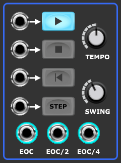
A trigger input and button to start PLAY.
A trigger input and button to STOP the sequencer.
A trigger input and button to RESET the sequencer to the first step.
A trigger Input and button to advance the sequencer to the next STEP. The trigger input serves as an external clock input and only has an effect when PLAY is engaged. When a cable is connected the internal clock is disabled.
A TEMPO knob that sets the rate of the internal clock. This knob is calibrated in BPM on the assumption that a bar consists of 16 steps and there are four beats to a bar.
A SWING knob that adjusts the timing ratio between odd and even steps of the internal clock. When set fully CCW (counter clockwise) each step is of equal length. When set fully CW the first step in a pair lasts twice as long as the second.
An EOC (End Of Cycle) socket that outputs a brief 5 V trigger when the last step of a sequence finishes.
An EOC/2 (End Of Cycle divided by two) socket that outputs a brief 5 V trigger at half the rate of EOC.
An EOC/4 (End Of Cycle divided by four) socket that outputs a brief 5 V trigger at a quarter of the rate of EOC.
Beneath the Transport area there are four sockets that enable control voltages to modify a range of parameters inside N-Step.
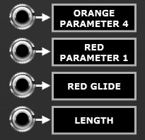
A left click on the selector to the right of a socket pops up a menu of the modulation destinations…
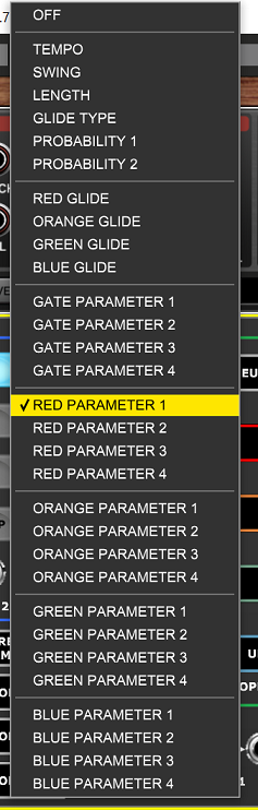
The voltage control maps directly to knob settings with 0 V being the minimum setting and 5 V the maximum.
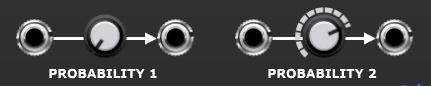
The N-Step Main module includes a couple of simple Bernoulli gates.
These are useful for introducing an element of chance in a number of situations. On receiving a gate or trigger input they decide depending on their probability setting whether to pass on the gate/trigger to their output.
When set at 50% they effectively toss a coin. When set at 0% they never pass anything on. At 100% they always pass on the gate/trigger.
Their probability can optionally be set by voltage control using the external CV facility discussed above so they offer considerable flexibility.
Next to the gates there’s a momentary action push button that outputs 5 V when pressed or 0 V otherwise.
This couldn’t be simpler but is handy for things like manually triggering multiple actions at once.
A CV channel’s RANGE selector controls the voltage range of channel’s output and also determines whether or not pitch quantization is applied. The 1 OCTAVE, 2 OCTAVES, 3 OCTAVES and 4 OCTAVES options all use quantization.
If nothing is connected to the QUANTIZE socket then the quantization is to the nearest semitone (i.e. the chromatic scale).

However, if an Adroit S-Poly chord or scale signal is fed in to the QUANTIZE input then the channel is quantized to fit that chord or scale.
If DYNAMIC TUNING is selected for the RANGE option then a novel alternative to quantization is applied. This is discussed later.
Each CV channel has a GLIDE knob that controls how quickly the channel’s output changes. When set full CCW changes happen instantly. In addition a four position switch provides some global control over how glide works.
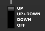
This can offer interesting creative control over portamento. For instance in the UP position pitch glides when rising but jumps when falling. Glide settings can also be subjected to voltage control so it’s possible (although not entirely straightforward) to program slides and bends on a note by note basis.
Gates/triggers
The ON buttons of the Aux modules enable you to set a rhythmical pattern. This can be done manually, via the use of operations or a combination of the two.
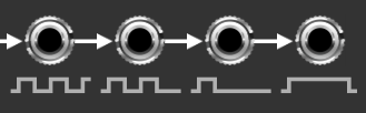
The Main module provides four simultaneously available but slightly different gate/trigger outputs.
Initially the easiest way to think about these outputs is that they vary in “speed” from fast on the left to slow on the right but the signals produced actually depend on the precise ON button pattern.
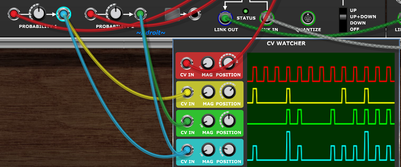
An example of a simple 8 step sequence using a single Aux module should make things clear.

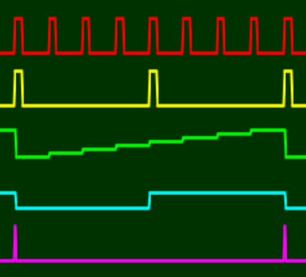
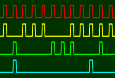
The red CV Watcher trace shows the output of the trigger/gate socket on the left, yellow the second output, green the third and cyan the final output on the right. For reference the magenta trace shows the trigger output from the step 1 trigger output of the Aux module.
Hopefully you can see how the graphical labels beneath each socket reflect the logic.
The first output fires at the beginning of every step change.
The second output fires at the beginning of every step that is on.
The third output fires at the beginning of the first step in a series of contiguously on steps.
The fourth output is high for the duration of any contiguously on steps. So if all the steps are on this output will be high all the time.
These give you a range of options for controlling envelope generators, clocking other sequencers and also the built-in sample and hold functionality described shortly.
The waveform image above shows the outputs when TEMPO is set at the default 120 BPM and the LENGTH knob is at the default 22 ms. If we adjust the LENGTH knob to the minimum 1 ms setting the following happens…
Increasing the LENGTH to 100 ms has the following effect…

Note that if the LENGTH exceeds the size of a step the signals still drop, albeit very briefly (so briefly that it’s difficult to see the drop using CV Watcher).
CV channels
The diagram below shows how the position of a knob on an Aux module is transformed into a final CV output. It’s how a CV channel might be structured if it were constructed using individual modules.
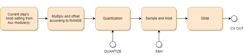
The following sections describe the process in more detail.
Range
Each CV channel has its own RANGE selector. A channel’s range determines exactly how the position of the Aux module knobs are mapped to CV outputs.
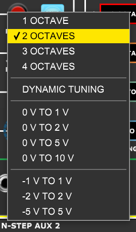
You will rountinely want to control pitch using N-Step and the top four options in the menu map the knob settings to either one, two, three or four octave ranges. A typical melody or bass line spans one or two octaves so you will probably use the 1 OCTAVE and 2 OCTAVES settings the most as it’s far easier to dial in the note you want when the knob range is small, but sometimes you’ll want to use the larger ranges.
| Range | Lowest note | Highest note |
|---|---|---|
| 1 OCTAVE | C2 | C3 |
| 2 OCTAVE | C2 | C4 |
| 3 OCTAVES | C2 | C5 |
| 4 OCTAVES | C2 | C6 |
As shown in the table above when using the OCTAVE range settings the lowest note available is always C2 (0 V in Voltage Modular) but you can adjust the base pitch in the sound modules as needed. For instance by using the “footage” settings provided by many oscillators.
When switching a channel between octave ranges a little menu pops up giving you a choice about how to manage the transition.
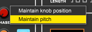
Let’s say you want to switch from 1 OCTAVE to 2 OCTAVES. This menu gives you the option to maintain the knob positions (which effectively doubles the size of the intervals) or to automatically adjust the knob positions so that the result produces exactly the same pitches as before.
When going in the opposite direction, say from 2 OCTAVES to 1 OCTAVE, the menu is slightly different because the sequence could contain pitches that are outside of the newly selected range.

Selecting Attempt to maintain pitch adjusts the knob positions but if it’s impossible to map an out of range pitch then it is lowered by one or more octaves in order to fit in range. This results in a musically coherent outcome because although the octave might change, an F# will always map to an F# for instance. In fact this adjustment can sometimes be used as a creative tool.
Sample and hold
Each CV channel has its own sample and hold (S&H) input socket. If nothing is connected to a channel’s S&H socket then sample and hold is bypassed and whatever CV’s are programmed into the sequence pass on to the glide processing unchanged.
So with no S&H input if the channel is controlling say pitch then no matter what rhythmical pattern is programmed into the ON buttons the pitch will change ever step (assuming that the CV channel’s knobs have varying settings).
In some circumstances this behaviour might be exactly what you want. But often you’ll want the pitch to only change if a step’s ON button is engaged. A third possibility is that you’ll want the pitch to only change at the beginning of the first step in a series of contiguously on steps.
This is where the sample and hold function comes in as it can freeze the CV/pitch in a controlled fashion.
Let’s illustrate this with the rhythm pattern we used previously when discussing gates/triggers.
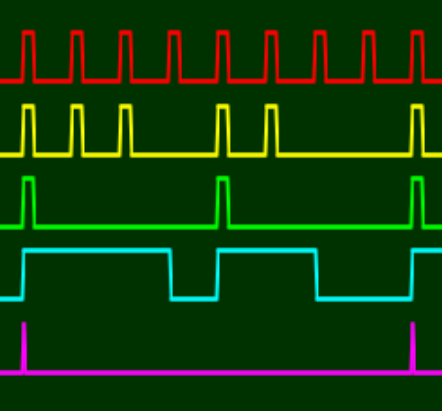
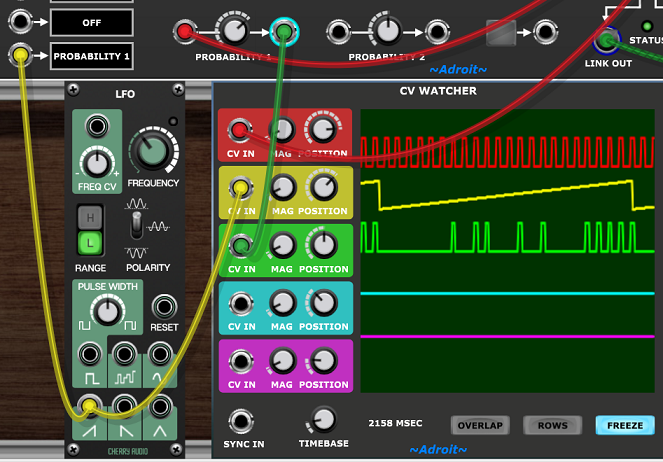
The image below shows various traces that demonstrate the effect of sample and hold on a rising CV step pattern (created using the RAMP operation discussed later)
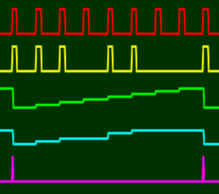
The red trace shows the leftmost gate/trigger output which produces a trigger pulse on each step change.
The yellow trace shows the second gate/trigger output. Compare this with the ON button pattern and you’ll see there’s a pulse for each step where the ON button is engaged.
The green trace shows the CV staircase without sample and hold applied.
The cyan trace shows the CV staircase with sample and hold applied using the signal shown in yellow as the S&H trigger.
The magenta trace shows the step 1 trigger output of the Aux module just as a reference to indicate where the sequence repeats.
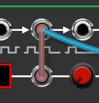
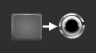
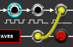
What’s important to notice here is how the signal shown in cyan holds its value steady in the gaps when steps don’t have their ON button enagaged. This is achieved by connecting the second gate/trigger output to the S&H input of the CV channel in question, as shown below using a yellow cable.

The third situation where you want the pitch to only change at the beginning of the first step in a series of contiguously on steps is just as easy to implement…
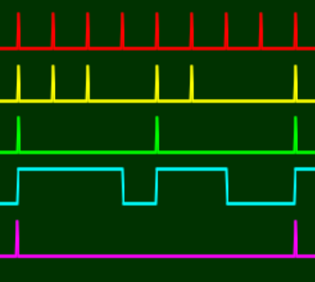
For completeness the traces involved in this situation are shown below.
There are only two pitches because there are only two sets of contiguously on steps in the pattern.
Propagation delay
One technical issue to be aware of concerning the use of sample and hold as discussed above is that the cable from the gate/trigger output to the S&H input introduces a one sample delay. So a CV subject to sample and hold changes 1/48,000th of a second after the gate/trigger pulse goes high. In the vast majority of cases this tiny delay (less than 21 microseconds) has no impact whatsoever but in certain situations it can cause a sound generating module that is very time sensitive to see pitches one step too late.
An example of this subtle problem is sending a gate/trigger from N-Step to the Adroit Granular Synth‘s SEED IN socket while sending an accompanying pitch CV (that has had S&H applied) to the Granular Synth’s 1 V/OCT input. What happens is that the seed is generated one sample before the pitch CV arrives and because grain pitch is fixed at the point of seeding the wrong (old) pitch is used instead of the one you want. The problem does not arise when the gate/trigger from N-Step is connected to the GATE input of the Granular synth and reasonably fast seeding rates are used.
The solution is simply to compensate by delaying the SEED IN signal by one sample too. You can do this by passing the gate/trigger through any neutral module such as a multiple. Another simple fix is to pass the gate/trigger through a spare one of N-Step’s own Bernoulli gates with its PROBABILTY set to 100%.
Note this subtle problem with propagation delays is not unique to N-Step, it’s something you might encounter in a number of situations where triggers and accompanying data don’t arrive in perfect sync. This can happen for instance when converting CV to MIDI if the signal paths are a bit convoluted. It’s not a major problem in practice and is generally easy to fix providing one is aware of the issue.
The GS Multiplex module (which is partly designed for linking an N-Step sequencer to a Granular Synth) has built-in propagation delay compensation. It uses a 4 stage delay line on each gate input so can cope with pitch information arriving up to 4 samples late.
Quantization and dynamic tuning
Using any of the OCTAVE range settings forces a channel to use pitch quantization. Aux knob settings then snap to the nearest semitone if nothing is plugged into the QUANTIZE socket. If an Adroit S-Poly chord or scale signal is fed to the QUANTIZE socket then values are quantized to the nearest note in the chord or scale.
Pitch sequences that use arbitary pitches (even when quantized to the nearest semitone) can sometimes sound a bit “out of tune”. This is fine if you want to produce twelve-tone serialism but you might often want to restrict the options by having some kind of chord or scale feeding the QUANTIZE input socket. This is why the LSSP Chord, Chord Memory and 8 to 1 Poly Switch modules are included in the N-Step bundle.
The novel DYNAMIC TUNING range option only works when a scale or chord signal is fed to the QUANTIZE input. This option is superficially similar to the regular quantization used when an OCTAVE range is selected but provides a more direct mapping. When DYNAMIC TUNING is selected whatever pitches there are in the scale or chord signal are uniformly distributed across the span of the Aux knobs. So if say the QUANTIZE input is a four note chord then the first quarter of a knob maps to the first note, the second quarter to the second note and so on.
This might seem just like regular quantization but is quite different as there’s an exact one-to-mapping between a note in the chord/scale signal and a segment of the knob position. In contrast regular quantization completely ignores the octave of any note in the chord/scale signal and takes the octave from the knob’s setting. Also with regular quantization the mapping is not guaranteed to be uniformly distributed.
In practical terms dynamic tuning sounds different to regular quantization in that the result is not just “in tune” but uses the exact same pitches as fed to the QUANTIZE socket – preserving the octaves rather than ignoring them. This difference is very noticeable if you play polyphonic signals into the QUANTIZE socket from a Chord Memory module that’s recording live from a MIDI keyboard.
Dynamic tuning is great for programming ideas using automated motif transposition/translation. Here you think of the CV sequencing in the Aux modules as using purely logical pitches, you program the absolute pitches into multiple Chord Memory modules (or other sources of S-Poly chord and scale signals) and then sequence these signals using the 8 to 1 Poly switch. This is essentially the same technique as used to create chord progressions but with dynamic tuning instead of regular quantization and will be discussed in more detail later.
Dynamic tuning is also useful if you want to build melodies that span a large range as otherwise it can be fiddly trying to pick out the right pitches.
You can of course mix dynamic tuning and regular quantization in the same module. You might for instance have one channel using dynamic tuning to create bass lines that track the lowest note in the chord while other channels use regular quantization.
The other RANGE options are simple in contrast as no quantization is applied to the knob values. The options vary from each other just in terms of the minimum and maximum values that can be represented by the knob settings.
Operations
An important aspect of N-Step is the ability to perform operations on channel data. Such operations provide a degree of automation that is extremely useful when working with lengthy sequences as making precise and repetitive manual adjustments to a large number of buttons or knobs is difficult and tiresome.
Operations also open up a range of creative possibilities where one can explore “what if?” ideas. For instance what if I try one voice performing a rising arpeggio with a seven note cycle against another performing a falling arpeggio with a five note cycle? Or maybe a six/five pattern would sound better? Doing such experiments manually would take ridiculous amounts of effort but with N-Step operations it’s just a matter of a tweaking one or two knobs.
Fans of generative music will also be happy to learn that operation parameters can be subjected to voltage control. So it’s possible to set up complex systems that mutate and evolve.
Operations can be triggered by an external trigger input or by clicking on a channel’s DO button.

Additionally if a channel’s AUTO button is engaged then any change in a parameter knob’s setting (either by manual tweaking or via external CV control) will automatically trigger an operation.
Generally operations apply to every Aux module connected in a Main module’s loop. However there are two special exceptions…

If an Aux module’s SOLO button is enaged this disables and bypasses any other Aux modules in the loop so that you can focus on just one part of a sequence and operations only apply to the soloed Aux module.
If an Aux module’s LOCK button is enaged the Aux module is protected from accidental changes and operations are ignored by the module.
Each channel has its own operation selector. Clicking on a selector pops up a menu where one can select the desired operation.
Note that just selecting a new operation does not trigger it.
There are two different classes of operation – Gate Channel Operations that apply to the ON buttons and CV Channel Operations that apply to the knob channels. So there are two different menus.

More operation options might be added in future updates but if so this wouldn’t affect your legacy patches.
Gate Channel Operations
| Operation | Parameter 1 | Parameter 2 | Parameter 3 | Parameter 4 |
|---|---|---|---|---|
| ALL ON | ||||
| ALL OFF | ||||
| RANDOM | PROBABILITY | |||
| PSEUDO RANDOM | PROBABILITY | SEED | OFFSET | |
| EUCLIDEAN | DENSITY | PERIOD | PHASE | |
| BINARY | DENSITY | PERIOD | PHASE | |
| AB PATTERN | A ON | A OFF | B ON | B OFF |
| INVERT | ||||
| REVERSE |
ALL ON – engages all ON buttons.
ALL OFF – disengages all ON butttons.
RANDOM – sets the ON buttons randomly. The PROBABILITY parameter controls the likelihood of an ON button being engaged. When DENSITY is 100% the operation is the same as ALL ON. When DENSITY is 0% the operation is the same as ALL OFF.
PSEUDO RANDOM – like the RANDOM operation this sets the ON buttons randomly however the behaviour is markedly different as the results are derived from a seed value. So if the parameters remain constant then the operation will produce the same result each time it executes.
There are three benefits of this approach over the RANDOM operation. Firstly it’s possible to “fade” a pattern in and out by varying the PROBABILITY parameter without the pattern changing wildly. Secondly it’s possible to shift the pattern forwards and backwards in time using the OFFSET parameter. Finally it’s possible to reproduce a pattern via identical SEED parameter settings (using the right-click Edit Value option for precision).
EUCLIDEAN – sets the ON buttons according to a Euclidean Rhythm algorithm. This spaces out the on steps of a repeating pattern as evenly as possible. The DENSITY parameter controls the percentage of steps that are on, the PERIOD parameter controls the duration of the pattern in steps and the PHASE parameter allows the pattern to be rotated.
BINARY – sets the ON buttons all in a bunch. It’s kind of like the opposite of the EUCLIDEAN operation. The DENSITY parameter controls the percentage of steps that are on over the number of steps set by PERIOD. PHASE rotates the pattern. So if say DENSITY is 50%, PERIOD is 10 and PHASE is 0% the pattern will consist of five on steps followed by five off steps.
AB PATTERN – sets the ON buttons in a alternating A/B pattern. It’s a little bit like having two BINARY operations in series. The pattern has four sections A ON, A OFF, B ON, B OFF. Each section’s duration is set by a corresponding parameter and can last from 0 to 16 steps. So the total duration of the pattern is all four values added together. One example might be 1, 2, 3, 4 this will create the 10 step pattern on, off, off, on, on, on, off, off, off, off. Note that a section that’s set to be 0 steps long is skipped so 0, 1, 2, 3 will create the 6 step pattern off, on, on, off, off, off.
INVERT – flips the state of all buttons.
REVERSE – reverses the order of the ON button pattern, but only within the boundaries of each Aux module rather than the entire sequence.
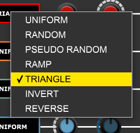
CV Channel Operations
| Operation | Parameter 1 | Parameter 2 | Parameter 3 | Parameter 4 |
|---|---|---|---|---|
| UNIFORM | VALUE | |||
| RANDOM | LIMIT 1 | LIMIT 2 | ||
| PSEUDO RANDOM | LIMIT 1 | LIMIT 2 | SEED | OFFSET |
| RAMP | LIMIT 1 | LIMIT 2 | PERIOD | PHASE |
| TRIANGLE | LIMIT 1 | LIMIT 2 | PERIOD | PHASE |
| INVERT | ||||
| REVERSE |
UNIFORM – sets all the knobs of the channel to the same value.
RANDOM – sets all the knobs of the channel randomly to values between LIMIT 1 and LIMIT 2.
PSEUDO RANDOM – as with the gate channel PSEUDO RANDOM operation this uses a seeding mechanism, producing similar benefits, but instead of a PROBABILITY parameter there are LIMIT 1 and LIMIT 2 parameters that enable you to set the range of values produced. The OFFSET parameter shifts the pattern forwards and backwards in time
RAMP – sets the knobs in a repeating pattern that lasts the number of steps set by the PERIOD parameter with values varying linearly between the LIMIT 1 parameter and the LIMIT 2 parameter. If LIMIT 2 is higher than LIMIT 1 then the ramp rises, if LIMIT 2 is lower than LIMIT 1 the ramp falls. The PHASE parameter allows the pattern to rotated.
TRIANGLE – similar to the RAMP operation but the pattern of knob settings goes in one direction then the other resulting in a triangular movement rather than a ramp.
INVERT – flips the setting of all knobs about the 12 o’clock center value.
REVERSE – reverses the order of the knob settings, but only within the boundaries of each Aux module rather than the entire sequence.
Using the end of cycle outputs
In the Main module’s transport section there are three output sockets labelled EOC, EOC/2 and EOC/4.

EOC stands for End Of Cycle and these sockets output a brief trigger pulse when the last step in a sequence completes, or when every second or fourth cycle completes.
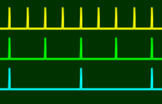
In the image above the yellow trace shows the pulses from EOC, green shows EOC/2 and cyan shows EOC/4.
EOC/2 and EOC/4 keep count of EOC and these counters are not reset by the sequencer starting and stopping. They are reset when the RESET button is pressed or a trigger is received by the socket on its left.

Perhaps the most obvious use of the EOC output is to make N-Step stop automatically after playing to the end of the sequence. To make the sequence play twice and then stop use the EOC/2 output. To make the sequence play four times and then stop use the EOC/4 output…
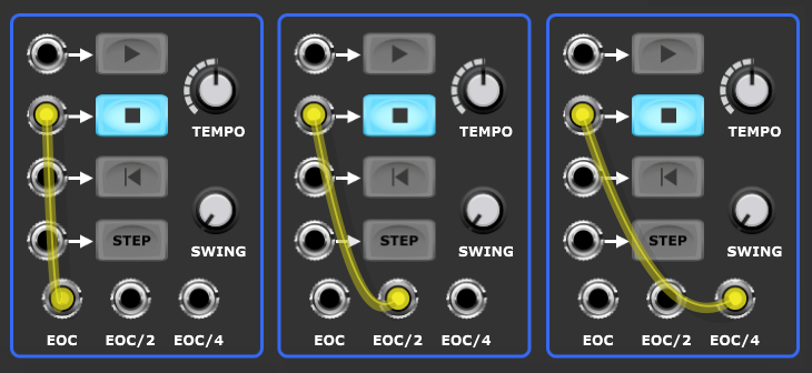
If you need more flexibility the N-Step Remote module can keep track of end of cycle triggers and stop the sequence after anything from 1 to 99 plays.

Another application is for chaining sequencers. Here’s an example of two N-Step sequencers playing in a loop…
There are no sound making modules in this patch, it’s just demonstrating chaining.
There are various other uses for the EOC outputs including using them to execute operations on channel data. This is done by patching an EOC output to the DO input socket of a channel and disengaging the channel’s AUTO button.
Most operations produce the same result every time they are executed unless their parameters change but RANDOM is an example of one that varies.
More sophiticated control would use the external CV inputs to set operation parameters prior to the DO trigger.
For instance here’s an example where the upper and lower limits of a RAMP operation are being slowly changed by a couple of LFO’s so that the ramp is in constant motion…
Note that the POLARITY switches on the LFOs are set so that their outputs vary between 0 V and 5 V so as to match the CV range of N-Step’s external CV inputs. Nothing bad will happen if you feed out-of-range voltages to the CV inputs as they are just clamped (so in the case of a bipolar LFO signal the negative half of the waveform would be treated as 0 V).
If you engage the red channels’s AUTO button you’ll see the AUX knobs animating too. But while this looks pretty it doesn’t add anything musically useful in this particular situation and is far less efficient than just executing the RAMP instruction once per end of cycle.
We’ll return to EOC applications later when looking at using it as an external clock for another N-Step sequencer.
Ancillary modules
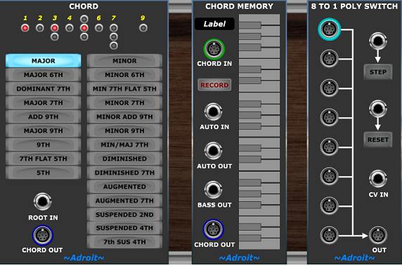
As well as the Main and Aux modules the N-Step bundle includes three ancillary modules that help with pitch control. These are Chord, Chord Memory and the 8 to 1 Poly Switch. These are borrowed from the Adroit LSSP system and are also shared with the Adroit Granular Synth.
Because they come from the LSSP system by default they have the LSSP classic skin. So when you first load the ancillary modules they will most likely look like this…
However you will probably want them to look closer in appearance to the N-Step Main and Aux modules, so to change their backgrounds right click on the ~Adroit~ logo at the bottom of each module. This only needs to be done once. They will then look like this…
If you have LSSP then an alternative mechanism is to use the Skin module. If you have LSSP you’ll also realise that there are many other modules that produce S-Poly signals beyond those borrowed here.
We’ve already looked briefly at the Chord Memory module in the Quick start guide where it was used to provide a scale for quantization. This utilized the S-Poly chord/scale signal ouput from CHORD OUT.
The Chord module also outputs an S-Poly signal from its CHORD OUT socket.
These S-Poly chord/scale signals are often connected directly to the QUANTIZE input of the N-Step Main module. But sometimes we want to be able to switch between multiple Chord and/or Chord Memory outputs in order to change the quantization on the fly. This is where the 8 to 1 Poly Switch module comes into play.
Each of these modules has its own documentation page – Chord, Chord Memory and 8 to 1 Poly Switch. The Chord Memory module is the most complicated of the three so it’s highly recommended that you read its documentation to get a better understanding of its various features as here we’ll be focusing just on how the ancillary modules can be used specifically with N-Step.
Controlling quantization with the Chord and Chord Memory modules
The Chord module provides preset chord types. This can be very useful for exploring the distinctive chord sounds. In the simplest situation where you just want a C chord then you can just plug a Chord module into the Main module’s QUANTIZE input. However you’ll usually want to be able to select the root note of the chord and one easy way of doing this is to use a Chord Memory module working in monophonic mode to feed a root to the Chord module like so…
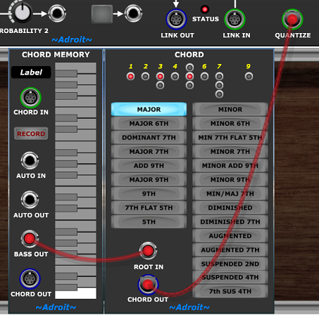
Now clicking on a key on the Chord Memory module’s little built-in keyboard selects a root note for the Chord module to use. If you engage the RECORD button on the Chord Memory module you can alternatively select the root note using a MIDI keyboard. Remember that the regular quantization in N-Step ignores the octave information in the QUANTIZE signal so all that matters is the note within the octave.
You’ll probably be curious about what notes are in the chord. And because Chord Memory is such a flexible module we can use another one in note watcher mode to show just that. Note that the second Chord Memory module’s RECORD button is engaged so that it’s recording the output of the Chord module.
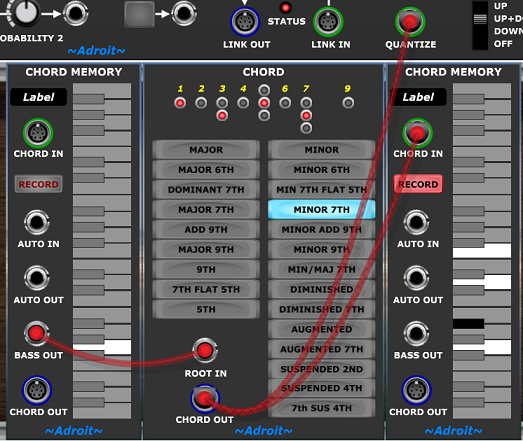
Here we see that a Gm7 contains the notes G, Bb, D and F.
If we wanted we could generate the same result directly by using just a Chord Memory module as shown below.
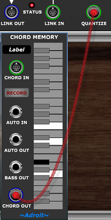
Again because Chord Memory is so flexible there are three different ways we could achieve the same result.
1) Modifying the earlier setup by removing the two unwanted modules and leaving the remaining Chord Memory remembering the chord. (You’d usually also disengage the RECORD button to prevent the chord being accidentally overwritten by any MIDI input).
2) Clicking on the required notes on the little built-in keyboard of the Chord Memory while its RECORD button is disengaged.
3) Playing a Gm7 on a MIDI keyboard while the Chord Memory module’s RECORD button is engaged.
The standalone Chord Memory module also enables us to remember a scale using either method 2 or method 3.
Hopefully you can now see how easy it is to control the quantization of N-Step. Next let’s look at how to sequence changes in quantization in order to create chord progressions.
Creating chord progressions
You can use any of the techniques discussed above to create multiple different chords and then switch between them using the 8 to 1 Poly Switch in order to create chord progressions.
As an example chord progression let’s go with the very popular I-V-vi-IV.
| I | V | vi | IV |
In C this is…
| C | G | Em | F |
This chord progression results in a slightly cheesy pop sound but such familiarity and simplicity are useful when exploring the basic mechanics.
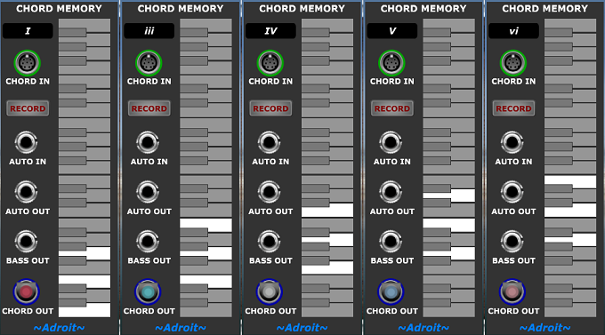
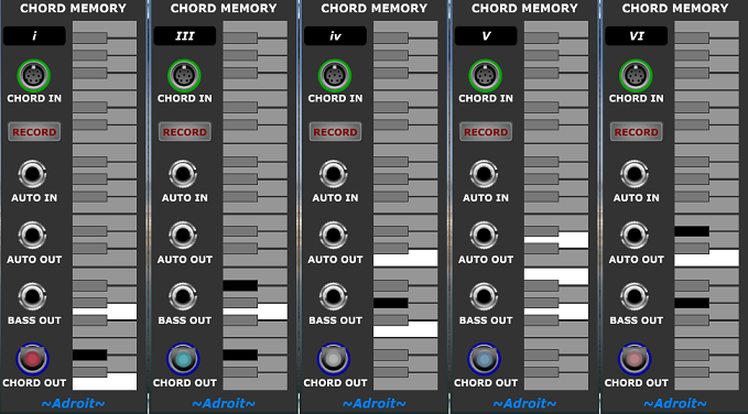
Let’s program four Chord Memory modules with these chords…
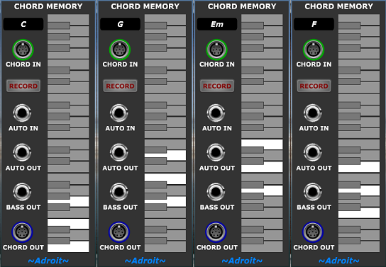
We can label them too just so that everything is as clear as possible.
Next we add an 8 to 1 Poly Switch and wire them together in the desired order.
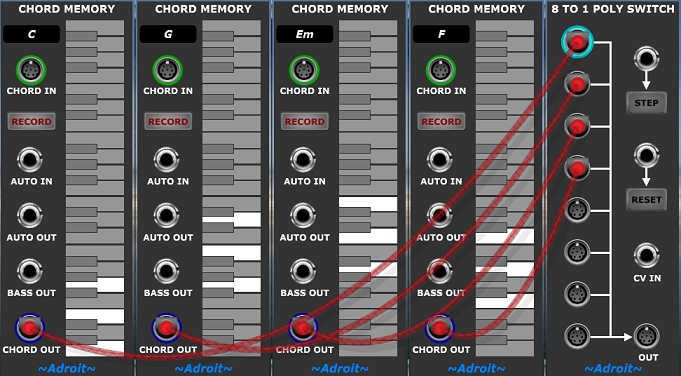
If you click on the Poly Switch module’s STEP button several times you’ll see the LED ring changing to show which input is selected, notice how the switch cycles through all connected inputs in a loop. Clicking on RESET returns us to the top-most connected input.
As you’ve no doubt already figured out, all we need to do to start testing this is to connect the OUT from the Poly Switch to the QUANTIZE input of the Main module and step through the chords with the STEP button while the sequencer is playing. But ultimately we want to have some kind of automatic coordination between the position in the sequence and the choice of chord.
There are two different approaches to this: trigger-driven and CV-driven.
Trigger-driven chord changes
Let’s load up a demo patch so that we can see and hear the trigger-driven method.
I did warn you it was cheesy!
In the top cabinet there’s the N-Step Main module and a couple of the really simple monosynths we used in the quick start quide. It sounds very basic indeed but this patch is just showing how to patch chord progressions not how to create fancy sounds. Obviously feel free to replace the crude monosynths with something that sounds better if you wish, but once you’ve worked your way through the following sections you’ll realise just how easy it is to sequence chord progressions with N-Step and you’ll be off building your own patches anyway.
In the middle cabinet there are four Aux modules wired up as a 32 step sequencer. The calibration of the TEMPO knob assumes that there are 16 steps to a bar but here we are using just 8 steps per bar – so 32 steps equates to a four bar loop.
All the ON buttons are initially engaged so that the effect of the quantization can be heard unambiguously but it sounds pretty monotonous as a result. Disengaging a few of the ON buttons helps add a little interest once you’ve listened to the thing loop a few times.
The red channel is programmed to send a rising 8 step arpeggio to the monosynth on the left. The orange channel is programmed to send a rising 6 step argeggio to the monosynth on the right. Because the pattern lengths are different there’s a polyrhythmic effect with the overall pattern only repeating after 24 steps.
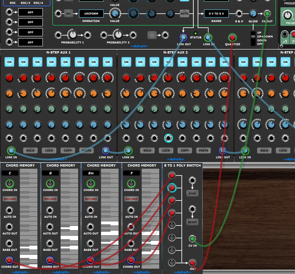
In the lower cabinet we have the four Chord Memory modules and the 8 to 1 Poly Switch that we’ve been discussing above.
The output of the Poly Switch feeds to the QUANTIZE input of the Main module as expected so the only new things here are the green cables from the Aux modules to the Poly Switch.
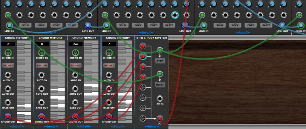
The trigger from the very first step is connected to the Poly Switch RESET input. This forces the Poly Switch to always use the first chord when the sequence begins.
The triggers from the first step of the next three Aux modules all feed the Poly Switch STEP input. These cause the Poly Switch to move to the next chord in the progression.
As you can see it’s all very straightforward and it’s easy to change the chords, chord progression length or the number of bars. It’s also flexible as you can trigger the chord changes on any step not just the beginning of a bar.
Even though this patch is the most bare-bones crude little demo, hopefully it has given you something of a lightbulb moment as being able to program chord progressions so easily greatly expands what you can achieve using N-Step.
CV-driven chord changes
The technique shown above is often the easiest way to create chord progressions but there’s another option…
The Chord Prog 2 patch sounds exactly like Chord Prog 1.
In Chord Prog 1 we treated the 8 to 1 Poly Switch a bit like a mini step sequencer with individual trigger outputs from the Aux modules instructing it to either reset or advance to the next input.
But in Chord Prog 2 we are controlling which input the Poly Switch passes on with a control voltage fed to its CV IN socket. When voltage controlled the Poly Switch maps voltages in the range 0 V to 5 V to evenly distributed bands with one band for each connected input (as explained in its documentation).
Any CV source such as an LFO could be used to select which chord to use but as before we want the choice of chord to depend on exactly where we are in the sequence. The elegant solution is to use a spare N-Step CV channel to control which chord N-Step uses to quantize its other CV channels. In this patch we are using the blue CV channel.
The wiring for this couldn’t be simpler, just one cable from the blue channel’s output to the CV IN of the Poly Switch…
Although only one cable is required, 32 knobs need to be set so you might be thinking that this is a really dumb idea. Well it does have its disadvantages but in this circumstance it’s relatively easy to set the knobs.
On the Main module the blue channel’s RANGE needs to be set to 0 V TO 5 V and the OPERATION needs to be set to UNIFORM. The channel’s AUTO button needs to be engaged too (it’s not engaged in the screenshots above but the reason for this will be explained in a moment).
It’s best if the sequencer is playing while doing the following because then we get instant feedback. Now we click on the first Aux module’s SOLO button to isolate the first bar. Then on the Main module we twiddle the blue channel’s VALUE knob in order to set all of the first Aux module’s blue knobs to the position that selects the first chord. You can see which chord is selected by looking at the LED ring on the Poly Switch module and you can also hear the result.
Then we click on the second Aux module’s SOLO button and twiddle the VALUE knob to select the second chord.
Then we click on the third Aux module’s SOLO button and twiddle the VALUE knob to select the third chord.
Then we click on the fourth Aux module’s SOLO button and twiddle the VALUE knob to select the fourth chord.
Finally we click again on the last SOLO button in order to cancel solo mode and return to normal.
Job done. Except it’s good practice to disengage the blue CV channel’s AUTO button otherwise accidentally tweaking the channel’s VALUE knob will wipe out the chord selections.
There are pros and cons for both approaches to selecting the chord. The trigger-driven method is probably slightly easier in most circumstance (and of course doesn’t use up one of the channels) but in some situations the CV-driven method wins out. For instance trying to combine step trigger-driven drum programming with trigger-driven chord progressions can result in a lot of cluttered wiring. Another problem with the trigger-driven method is that you might run out of inputs on the 8 to 1 Poly Switch when dealing with large sequences.
As we’ll see later the CV-driven method comes into its own in hierarchical patches where you have a slow running sequencer that has a channel dedicated to selecting chords.
More on chord progressions
So far the duration of the sequence and the duration of the chord progression have been the same but what about when they don’t match?
If the chord progression repeats or there’s more than one chord progression during the sequence then using the trigger-driven method we just need to add more cables or when using the CV-driven method we simply set more knobs.
However what about when the chord progression lasts longer than the sequence? Then the CV-driven method doesn’t work (unless the CV is controlled by another sequencer) but we can still use the trigger-driven method.
The simplest example of this situation is when we have just a single Aux module playing over and over but the chord changes each time it plays.
The easiest way to make this work is to connect the Main module’s EOC output to the 8 to 1 Poly Switch’s STEP input. Then each time the sequence completes (and restarts) the next chord is selected.
But there is a slight vulnerability in this approach in that if for some reason we want to restart from the beginning while midway through the chord progression (for example by clicking on the Main module’s RESET button) then the Poly Switch module doesn’t get reset. In the Chord Prog 1 patch it would be reset because the trigger output for the very first step in the sequence is wired to the Poly Switch’s RESET input. And in the Chord 2 patch is would be correct because the CV directly controls the choice of chord.
We could ignore this vulnerability but that’s not good practice.
When running Voltage Modular in standalone mode one solution is to use the push button feature of the Main module wired so that a click on the push button always forces a reliable start/restart. When running Voltage Modular inside a DAW then the same cables would be connected to the I/O Panel’s PLAY socket.
Let’s look at a patch that implements the above (standalone version)…
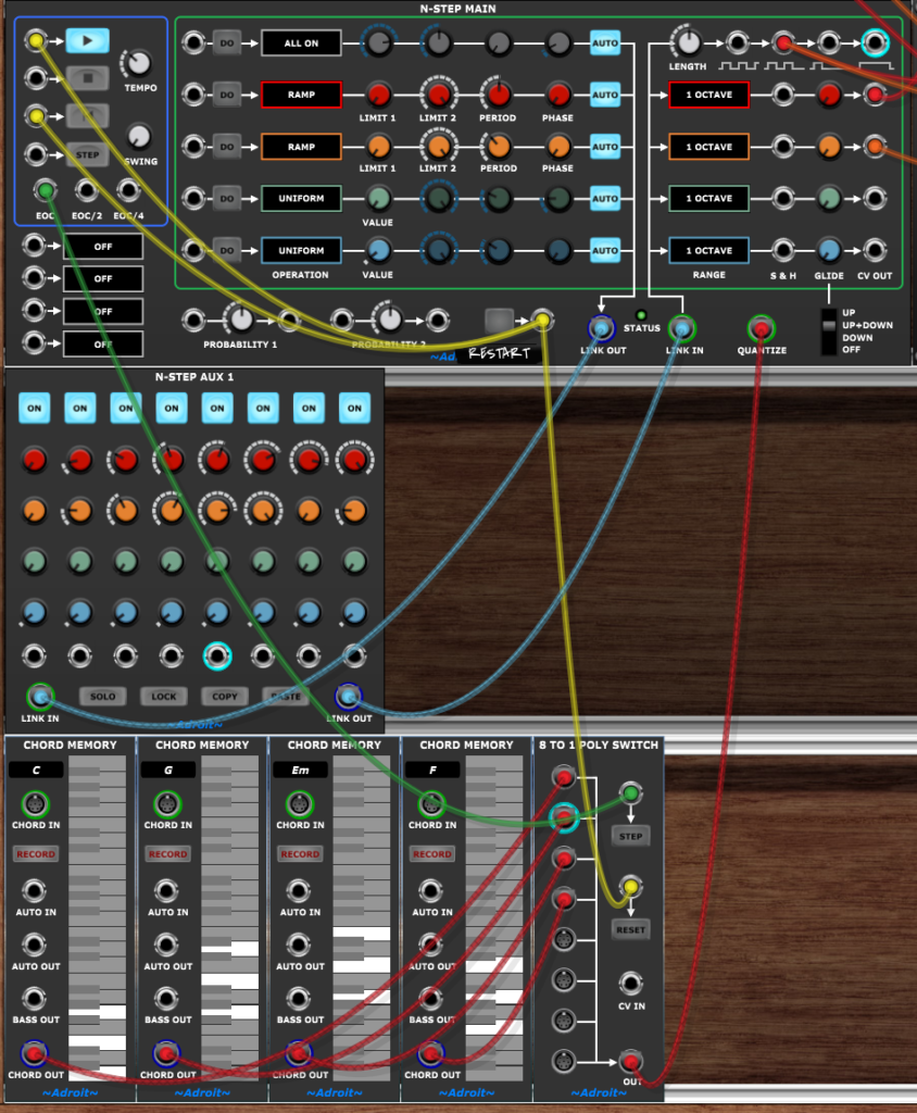
The green cable advances the Poly Switch to the next chord in the progression each time the cycle ends.
The yellow cables make the push button reset the sequencer and start it playing as well as making the Poly Switch reset so that the chord progression starts on the correct chord. The push button has been labelled “RESTART” so that when we come back to the patch later we know what the button does.
An alternative to using the push button would be to add an N-Step Remote module to the patch but that’s a bit over the top in a simple patch. In more complex patches N-Step Remote is almost essential though as it allows all transport and sync funtions to be brought together in one place.
Syncing to a DAW
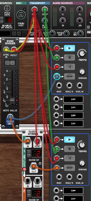
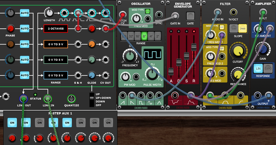
So far we’ve been using N-Step as a standalone sequencer with its own internal clock but the input sockets in the transport area (outlined in blue) enable N-Step to sync to a DAW host instead, as shown in the image below.
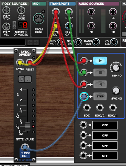
This uses the PLAY, STOP and SYNC OUT signals provided by Voltage Modular’s I/O Panel.
PLAY outputs a trigger when the DAW goes into play mode.
STOP transmits a trigger when the DAW stops.
SYNC OUT sends 96 pulses per quarter note at the tempo used by the DAW. This sync signal is sent via the yellow cable to a Sync Divider module which counts the pulses according to its NOTE VALUE setting. This generates a clock signal that instructs N-Step Main to advance one step. As the NOTE VALUE setting is 1/16th in the example above, N-Step’s STEP input receives a clock pulse every sixteenth note (which works out as every 24th sync pulse).
The red cables from PLAY send a play trigger to start N-Step playing and also reset triggers to ensure that both N-Step and the Sync Divider start at the beginning of their cycles.
Finally the green cable makes N-Step stop when the DAW stops.
Using multiple N-Step sequencers
Although N-Step takes up a lot of screen space its CPU use is fairly modest so it should be feasible to use multiple N-Step sequencers in a single patch. Part of the constraint depends on what sound generating modules you want to use as typically the more sequencers you use the more sound generating modules you’ll be using too.
The CPU load increases not just with each N-Step Main module added but also for each Aux module as a lot of information flows through the chain and each Aux module has to pass this information on.
You should find that CPU loads increases in a linear fashion as you add modules but before investing too much time in incrementally building a large project it might be a good idea to build a rough model early on to test what scale of project your computer is capable of supporting before audible glitches start to occur.
When using multiple N-Steps you’ll find that it soon becomes impossible to fit everything on screen so you’ll end up zooming in and out and doing a fair amount of scrolling. To help make this manageable the recommended layout is vertical with each “track” (i.e. a sequencer plus associated sound generation modules) occupying two cabinets.
One possible cabinet layout scheme is…
| N-Step Remote, scales, chords etc | Mixing and effects |
| N-Step Main module for Track 1 | Sound generating modules for Track 1 |
| N-Step Aux modules for Track 1 | Extra modules for Track 1 |
| … | … |
| N-Step Main module for Track N | Sound generating modules for Track N |
| N-Step Aux modules for Track N | Extra modules for Track N |
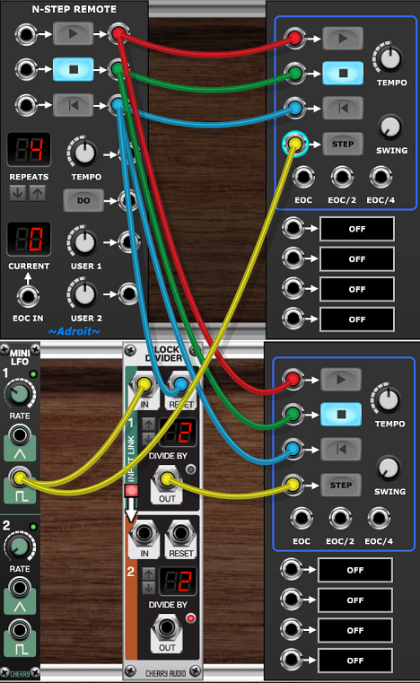
When using multiple sequencers in standalone mode you’ll want to use the N-Step Remote module as it enables you to set a global tempo and start playback with a single button press. It’s recommended that the N-Step Remote module is placed on the left at the top of the patch so that it’s easy to find.
Let’s look at an example called Mellow that uses two N-Step sequencers (and the layout suggested above).
The N-Step Remote module keeps everything in sync using the following connections.
PLAY to both N-Step Main’s PLAY inputs.
STOP to both N-Step Main’s STOP inputs.
RESET to both N-Step Main’s RESET inputs and the 8 to 1 Poly Switch’s RESET input..
TEMPO to both N-Step Main’s first external CV input (which is configured to control tempo).
By the way resetting an N-Step sequencer not only takes it back to the first step it also resets its internal clock. Beginning play also resets the internal clock. This helps eliminate small-scale timing issues where one sequencer might lag behind another by a fraction of a step.
Note that the upper sequencer has 32 steps while the lower one has only 16 steps. But they both play at the same rate, it’s just that the lower one plays twice for every one play of the upper.
The cable from the EOC/2 output of the upper sequencer to the NEXT input of the 8 to 1 Poly Switch drives a two chord vamp that changes chord every second play of the upper sequencer (and every fourth play of the lower sequencer).
The S-Poly signal from the 8 to 1 Poly Switch feeds the QUANTIZE inputs of both sequencers so all notes belong to the current chord.
To the right of the upper sequencer we have a simple duophonic sound generator. The sawtooth oscillator’s pitch is controlled by the red channel and the triangle wave oscillator is controlled by the orange channel. The green channel is used to control the cutoff frequency of the shared filter.
Three of the upper sequencer’s individual step trigger outputs drive a soft snare sound.
The lower sequencer provides a bass line using the same old simple monosynth configuration we’ve deployed before. The red channel controls pitch while the orange channel modulates the filter.
Three of the lower sequencer’s individual trigger outputs drive a kick drum. Note that because the lower sequencer repeats faster than the upper one it saves wiring doing it this way rather than using the upper sequencer’s trigger outs.
Running multiple sequencers at different speeds
In the Mellow patch example above both sequencers are running at the same speed but it’s often useful if one sequencer runs at say half the speed of the other. There are a number of different approaches to this.
One is to adjust the voltage that’s controlling N-Step’s tempo. The 0 V to 5 V CV maps to 30 BPM to 480 BPM in an exponential fashion. The BPM range can be looked at as four doublings i.e. 0 V = 30 BPM, 1.25 V = 60 BPM, 2.5 V = 120 BPM, 3.75 = 240 BPM, 5 V = 480 BPM so the CV is effectively using a 1.25 V per octave scale.
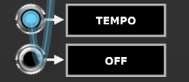
So by adding or subtracting 1.25 V the tempo will double or halve. We can do this by patching an output from a DC Source module to the tempo CV input of the N-Step Main we want to speed up or slow down.
The image below shows a modification to the Mellow patch. The DC AMOUNT knob is set to exactly -1.25 V (using the right-click Edit Value method). So the red cable is carrying -1.25 V and by patching it to the CV input controlling the tempo of the lower sequencer we are adding -1.25 V to the voltage from the N-Step Remote. Adding a negative number is the same as subtracting a positive number so the resulting voltage is the N-Step Remote tempo CV minus 1.25 V and because we’ve already established that the tempo CV is using 1.25 V per octave the result is that the sequencer plays at half the speed set by the Remote TEMPO knob.
Note that after doing the modification it’s likely that the two sequencers will be out of sync so you’ll need to restart them.
You can check that the result is as expected by hovering the mouse over the three TEMPO knobs. The Remote one and the upper sequencer one will be 110 BPM while the lower one wil be 55 BPM. You could just manually set one sequencer to 110 BPM and the other to 55 BPM but by automating things it means you can vary the tempo using the N-Step Remote module’s TEMPO knob and the ratio will remain correct.
When you manually adjust knobs the actual values you end up with can sometimes be a tiny amount off. In general when you need a knob to have an exact value you should use the right-click Edit Value method and type in the value required.
One limitation of using the voltage controlled approach is that N-Step clips its external CV inputs to the range 0 V to 5 V so it’s not possible to make any of the sequencers run below 30 BPM or above 480 BPM.
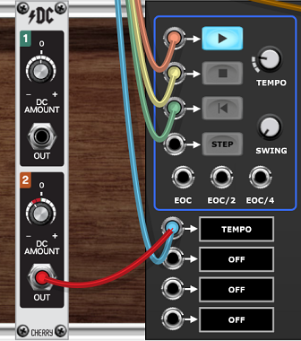
A second approach is to use an external clock and a clock divider. If syncing to a DAW host then one can insert a Clock Divider module to slow down one of the sequencers.
The image above shows a modification of the patch we looked at in the Syncing to a Daw section earlier. We need to duplicate some of the wiring to make sure the second sequencer starts and stops properly and also note that the Clock Divider needs a reset too otherwise it could end up out of sync on a restart.
By the way these sync issues aren’t anything unique to N-Step, whenever you use any modules that have an internal count state you’ll encounter the same problems. As an aside the tiresome wiring needed to keep things in sync using fragile clocks and triggers is one of the reasons why LSSP uses V/Bar.
In a standalone setup we can use any old clock source as a external clock if we set tempo by ear (or Hz).
In the example above the Mini LFO is being used to set the tempo. If you want more control over tempo then you could replace the LFO with a Sync Generator and Sync Divider.
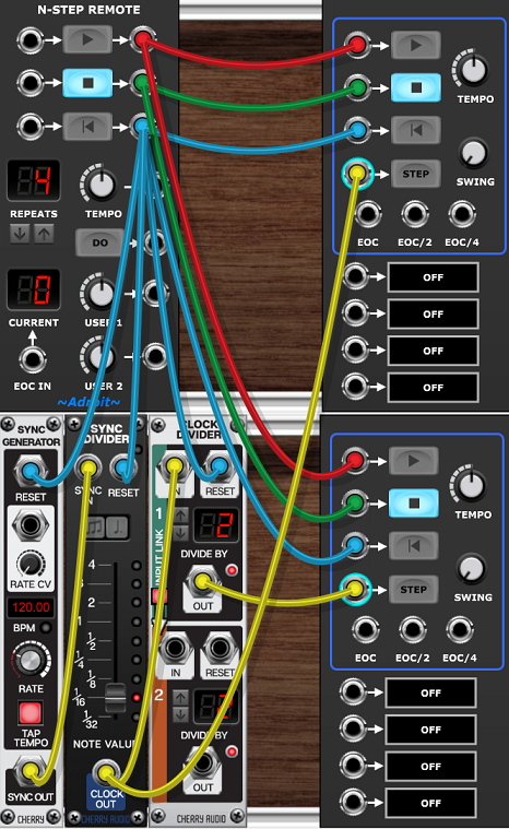
Again note the reset wiring (using cyan colored cables) to ensure everything remains in sync.
As you can see simply adding -1.25 V to the tempo CV is the easiest option providing you don’t need to go below 30 BPM and don’t need to sync to an external clock.
Hierarchical sequencing and some generative ideas
A third approach to running N-Step sequencers at different rates is to advance one sequencer by connecting its NEXT input to one of another sequencer’s end of cycle outputs. A variant on this is to use one or more of the individual step trigger outputs instead of EOC – this enables very flexible timing.
This third approach can be thought of as two-level hierarchical sequencing and can be very economical as one can use quite short sequences for the upper/fast level and introduce variations with the lower/slow level.
The following generative patch demonstrates this approach and also shows off a few other tricks.
If you click the DO button on the N-Step Remote module in the top-left corner then the patch will generate a new short tune.
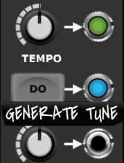
The sounds generated are fairly primitive and the tunes produced aren’t always brilliant but it shows the potential. If you click the DO button over and over then every now and then it will produce something interesting. You might stumbling across chord progressions or other elements that you could reuse in a “proper” patch.
Randomization only occurs when the “GENERATE TUNE” DO button is clicked. So the results after that are entirely deterministic which can sound rather mechanical after many repetitions. Later we’ll look at some modifications you might make to introduce live elements of chance.
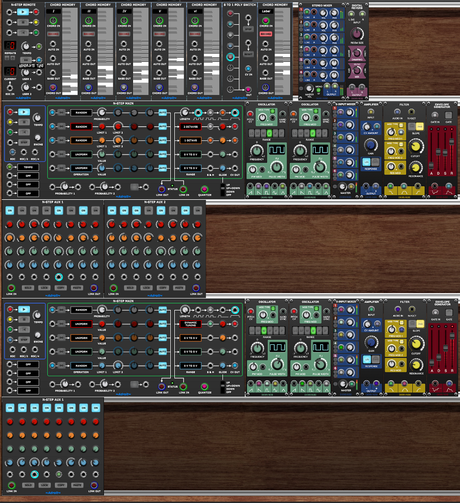
In the top cabinet we have the N-Step Remote module where you can start and stop play and set the tempo as well as hit the “GENERATE TUNE” DO button.
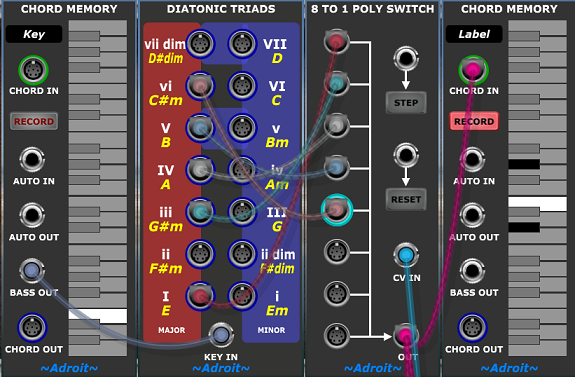
Then we have five Chord Memory modules programmed with the five most popular diatonic triads of the C major scale. They are labelled with standard roman numerals to help you identify the chords. Uppercase ones are major, lowercase minor.
The Chord Memory modules are wired to five inputs of an 8 to 1 Poly Switch, the output of which is fed to the QUANTIZE inputs of both N-Step sequencers and also to another Chord Memory module on the right. This extra Chord Memory module has its RECORD button engaged so its serving as a useful display for which chord is being output by the Poly Switch.
Next we have a mixer and a reverb module. Channel 1 of the mixer is the main output of the simple synth controlled by the upper/fast sequencer, Channel 3 is the main output of the synth controlled by the lower/slower sequencer. Channel 2 and 4 are fed with the bandpass outputs of the synth’s filters. These channels are used just to add a bit of stereo width to the otherwise monophonic sources. You can also play with the levels to get a certain amount of color variation. Each little synth has a mixer too that enables you to dial in different waveforms mixes from the oscillators.
The second and third cabinets house the upper/fast sequencer and the sound generating modules controlled by it. The sequencer has 16 steps so you can think of it as a single bar or two bars in duration depending on tempo.
The fourth and fifth cabinets house the lower/slow sequencer and the sound generating modules controlled by it. This sequencer is clocked by the EOC output from the upper/fast sequencer and is also limited to four steps by the cable connecting its 5th step trigger output to its RESET input.
So the upper/fast sequencer plays a complete cycle for each step of the lower/slow sequencer and the patch exploits this by using the blue channel of the lower/slow sequencer to select which chord to use for each cycle. This is done by connecting the 0 V to 5 V signal from the blue CV channel output on the lower N-Step Main module to the CV IN socket of the Poly Switch. Therefore the first four blue knobs on the lower Aux module select which chord to use for the first, second, third and fourth repeat of the upper/fast sequence. The choice of I, iii, IV, V or vi chord is spread out evenly across the span of each knob (fully CCW is I, fully CW is vi).
You could drag the lower Aux module and position it between the Poly Switch and the display Memory module if you liked…
This would help if manually selecting the chord. However in this patch the idea is that the choice of chords is made automatically every time you click on the “GENERATE TUNE” DO button. This is achieved by connecting this button’s output to the DO trigger input of the lower Main module’s blue CV channel and programming the channel to execute a RANDOM operation (with the LIMIT 1 and LIMIT 2 knobs being set so that the random choice can be any of the five chords).
There are 625 possible outcomes of the chord progression randomization although some of these won’t be particularly interesting – five of the outcomes are for instance just the same chord repeated four times.
The gate/trigger channel and the red CV channel of the lower sequencer drive a simple two oscillator bass synth.
The gate/trigger operation is set to RANDOM and triggered by the “GENERATE TUNE” DO button. The PROBABILITY is set to 80% so that sometimes a bass note is dropped. This is useful as the bass notes last for the duration of the entire upper/fast sequence and dropping one or two can create more interest. The LENGTH knob is turned up so that the gate lasts for 500 ms.
All of the red Aux knobs are fully CCW and the red CV channel’s RANGE is set to DYNAMIC TUNING. This means that the red CV output is the root note of the current chord fed to the module’s QUANTIZE input.
The gate output also feeds the S&H (sample and hold) input of the red CV channel so if the ON button for the current step is disengaged the pitch holds over from the last chord. Providing that the release time of the envelope generator is set long enough this can produce a musically useful pedal point as the bass note might not belong to the current chord.
Turning to the upper/fast sequencer, this is used to drive another simple two-oscillator synth except this time each oscillator has its own CV channel so we get a little bit of counterpoint. The oscillators are mixed together and share the same VCA, filter and envelope generator so it’s a duophonic rather than polyphonic setup. However the two pitches have different sample and hold behaviour so the lower pitched (orange channel) oscillator sustains pitches longer than the higher (red channel) pitched one.
The red CV channel also has a small amount of glide/portamento applied and a larger RANGE setting of two octaves rather than one.
The gate/trigger channel and both the red and orange CV channels are randomized when the “GENERATE TUNE” DO button is clicked.
The gate/trigger PROBABILITY is set to 70% so that some breathing space is added to the rhythm but turn it up to 100% if you want something more “electronic” feeling. However if you do this then unplug the orange cable feeding the S&H input of the orange CV channel otherwise it’ll drone on playing the same note all of the time.
The LIMIT 2 knob on the red CV channel is set to G3 rather than all the way up to C4. This is because the channel’s RANGE setting is two octaves and that’s slightly too wide a range. So by turning down the knob the range is limited to one octave and a fifth which produces a more musical result (to my ear at least).
Using different keys
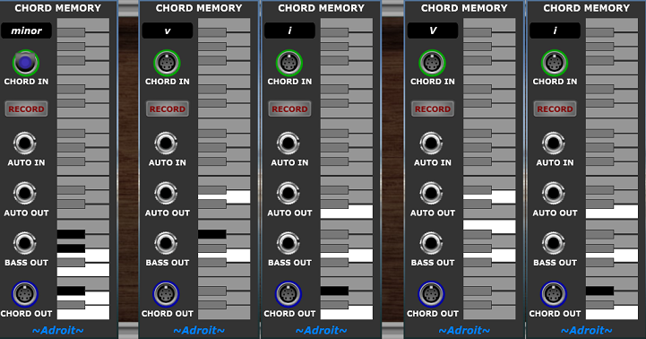
The patch we’ve been using generates tunes in a major key because the Chord Memory modules are all programmed with chords diatonic to the C major scale. So here’s a version that uses chords diatonic to C minor instead…
This is the same as the Generator Major patch except for the chords programmed into the Chord Memory modules and the use of a slower default tempo.
One slightly confusing thing here is that we have a major V when strictly speaking only a minor v chord is diatonic in minor. I call this the v v V thing and it’s about the leading tone. Basically the technically correct v is routinely replaced by the “wrong” V. The reason being that the dominant to tonic motion of V-i sounds much stronger than v-i because the third moves a half step instead of a whole step in resolution.
So in a minor key the minor third of the fifth chord is often raised a semitone to a major third.
In C minor therefore Bb is replaced by B (even though B is not in the C natural minor scale) because the motion from Bb to C has weaker resolution than B to C.
It’s also why in harmonic minor and melodic minor scales the 7th is major rather than minor. The image below and documentation on the minor scales module in LSSP might be helpful.
Don’t worry if this all sounds like gobbledygook, I just wanted to try and explain what might look like an inconsistency.
Ok so we can now make the Generator idea work in either C major or C minor but we are still stuck with C as the tonic. This has been useful so far as it’s far easier to work in C major than any other key simply because of the way the keyboard is laid out but how do we transpose to other keys?
Ideally we’d want to be able to transpose “at source” so that the Chord Memory modules displayed the actual chords used after transposition but unfortunately without borrowing more from LSSP it would be a bit unwieldy to do this. So we’ll look at doing the transposition the easy way by just adding an offset to all the oscillator’s PITCH CV inputs.
In the image above we’ve added another Chord Memory module to the top cabinet and wired its BASS OUT signal to each of the four oscillators’ PITCH CV inputs alongside the existing connections. This simply adds whatever the BASS OUT voltage is to the existing 1 V/Octave signals.
When a Chord Memory module’s only connection is via its BASS OUT socket it works in monophonic mode so when you click on its built-in keyboard only one note at a time is selected.
With the BASS OUT wired up can use the bottom octave of the Chord Memory’s keyboard to generate offsets from 0 V (the bottom C) up in semitone steps. In the image above the E key was clicked so the resulting voltage is 4 / 12 V which when added to the pitch CVs transposes everything up by 4 semitones to the key of E. If the resulting pitch becomes too high then you can drop everything an octave by adjusting the oscillators’ “footage”.
Just in case you are wondering how you’d implement the transposition “at source” using LSSP you’d probably do this..
If you wanted to see the individual chords too then you’d just add more modules doing note watcher duties like the Chord Memory on the right, but looking at the individual outputs from the Diatonic Triads module rather than the output of the Poly Switch.
Using the Bernoulli gates
Adding elements of chance was mentioned before but so far we’ve only discussed the Bernoulli Gates in passing. Here we’ll look at them in more detail and examine a few applications.
To recap – on receiving a gate or trigger input a Bernoulli Gate decides depending on its probability setting whether to pass on the gate/trigger to the output.
Note this behaviour is slightly different to some Bernoulli Gates.
When set at 50% they effectively toss a coin. When set at 0% they never pass anything on. At 100% they always pass on the gate/trigger.
Their probability can optionally be set by voltage control using the external CV facility.
Normally a gate/trigger signal (from one of N-Step’s gate/trigger outputs, from an individual step’s trigger output or even from an EOC output) is fed directly to an envelope generator’s gate input, the trigger input of something like a drum module, one of N-Step’s own S&H inputs or perhaps the clock input of another sequencer.
But a Bernoulli Gate can be inserted into this path. Then the gate/trigger may or may not arrive at its destination depending on the probability. This can add life to an otherwise repetitive patch. Small probabilities or large probabilities are particularly useful as this means an event occurs just once in a while or an event is dropped just once in a while. This feels more like improvisation than 50% probability which somehow feels more “random”.
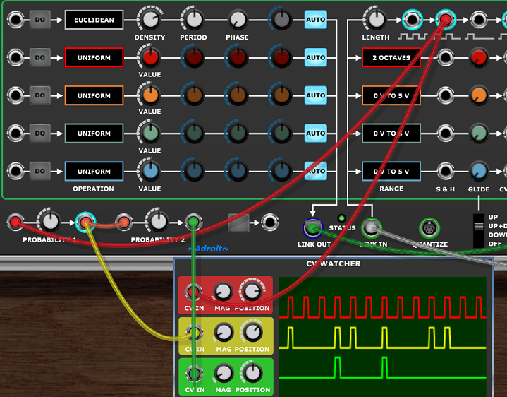
It’s kind of obvious how a Bernoulli Gate works but let’s look at some traces to ensure that we have something solid to base further discussion on.
The red trace shows a stream of pulses from an N-Step sequencer gate/trigger output with all steps on. The yellow trace shows this sent through a Bernoulli Gate with 75% probability, the green trace through one with 50% probability and the cyan trace through one with 25% probability.
This is called parallel wiring as each gate receives the same input (the red trace). The key thing to note is that an output can only be high when the Bernoulli Gate’s input is high, but also each output is independent of the other as the only commonality is that all three gates receive the same input.
An alternative is called series wiring where the output of one Bernoulli Gate is fed to the input of another.
Here the green trace is only high if the second Bernoulli Gate passes the signal and the first Bernoulli Gate passes the signal and the original (red) trace is high. Therefore series wiring performs a logical AND operation. This might be useful if say the yellow signal was firing a hi-hat and the green signal a snare and we wanted the snare to always be accompaned by a hi-hat but not the other way around.
Now let’s look at a third situation where we combine two different signals (created by parallel wiring from a common source).
Both Bernoulli gates are receiving the same signal (shown in red) They are both set at 50% probability but as they are independently making decisions their outputs (shown in yellow and green) differ much of the time.
The cyan trace shows the effect of patching both of the outputs into a single input. This adds the voltages together, so the highest peaks of the cyan signal are 10 V instead of the regular 5 V.
This is called analog ORing because modules looking for trigger or gate signals are only interested in whether an input is above or below a threshold (a threshold that is usually 2.5 V but certainly above 0 V and below 5 V). So whether the signal is 5 V or 10 V doesn’t matter – it is seen as high. Therefore adding two gate/trigger signals together effectively performs a logical OR operation.
A Bernoulli Gate’s probability is normally set by its knob but external CV control can be used instead. This introduces yet another interesting operation.
Here the likelihood of a gate/trigger signal passing the Bernoulli Gate can be modulated in real-time by another signal. When the CV is 0 V or 5 V the probability is 0% or 100% so the gate performs like a regular logic gate but intermediate values produce a kind of fuzzy probablistic ANDing.
Hopefully you can see from the above that Bernoulli Gates can add quite a variety of signal modifications into a patch. Now we’ll look at few practical examples based on a simple scenario using the setup illustrated in the image below…
We could drop some notes entirely by inserting a Bernoulli Gate.
Note this can also be viewed as adding some notes. The perspective depends on the probability setting. If the setting is high then it seems like notes are sometimes dropped but if the probability is low then one perceives that notes are sometimes added.
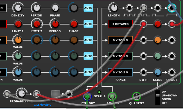
The obvious element of this is that the connection to the envelope generator has had a Bernoulli Gate inserted into it. What’s less obvious is that we needed to move the S&H cable too. This is because (most times as least) when a note is dropped you don’t want any spurious pitch change occuring while the previous note decays.
You might want that effect but if so you’d probably have started with this…
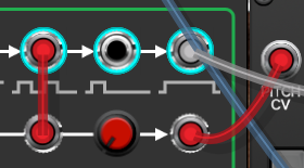
But if you do want to keep the pitch change while the envelope gate is sometimes dropped then leave the S&H connection as it was. This is a bit like moving fret position but not always plucking on a guitar.
If you want the opposite to happen – so that the envelope fires on all on steps but the pitch sometimes doesn’t change then use this wiring…
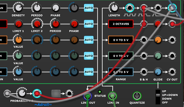
This is a bit like plucking but not always moving fret position. Note this won’t do anything interesting if every step in the gate/trigger pattern is on.
Adding one extra cable produces behaviour where sometimes notes are tied…
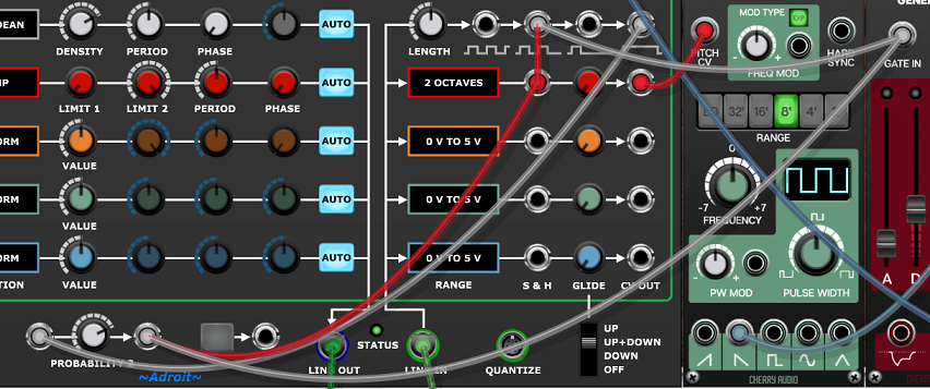
In this instance what I mean by tie isn’t a slur but the extension in time of the first note of a pair over the second note, ignoring the pitch of the second note. Actually this applies to however many contiguous steps are on, it’s not limited to just pairs. Again this won’t do anything interesting if every step in the gate/trigger pattern is on.
This latter wiring is useful musically as it can sound like a player naturally improvising but it’s not entirely obvious how it works so let’s take a closer look.
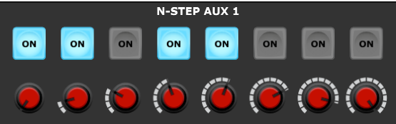
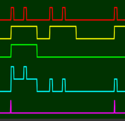
The red trace above is the second gate/trigger output i.e. a pulse for each on step in the pattern.
The yellow trace is the fourth gate/trigger output. i.e. a gate that’s high for the duration of any contiguously on steps.
The green trace is the output of the Bernoulli Gate i.e the yellow signal processed by the gate, so in this case the Bernoulli Gate has “decided” to tie the first two notes but not the second two.
The cyan trace is the analog ORed combination of the red and green signals. It’s this signal that is received by both the envelope generator and the S&H.
The magenta trace is just the trigger out from step one of the sequence for reference purposes.
The traces below show the impact of the cyan signal on the pitch…
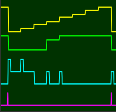
The cyan and magenta traces are as before but this time the yellow trace shows the pitch CV prior to sample and hold. i.e. the staircase caused by the positions of the red knobs (which where set by a RAMP operation).
The green trace shows the pitch CV after going though S&H. Note that the pitch only changes when the cyan signal transitions from low to high. Therefore because the Bernoulli Gate decided to tie the first pair of notes the pitch of the first note is held and the second pitch is ignored however the third and fourth notes are not tied and appear as independent notes.
The envelope generator gate input sees the 10V peaks as no different to 5 V and just interprets the cyan signal as one long note followed by two short notes.
There are lots of other ways of combining gates, triggers, sample and hold and Bernoulli Gates but we are approaching the point of information overload now so it’s perhaps best to leave it to your imagination and exploration…
Availability
Click HERE to visit the Cherry Audio store to demo or purchase the N-Step bundle.