Click here for an overview of the Drum Sequencer module.
Table of Contents
Basic operation
To function, the Drum Sequencer needs to be driven by a V/Bar signal.
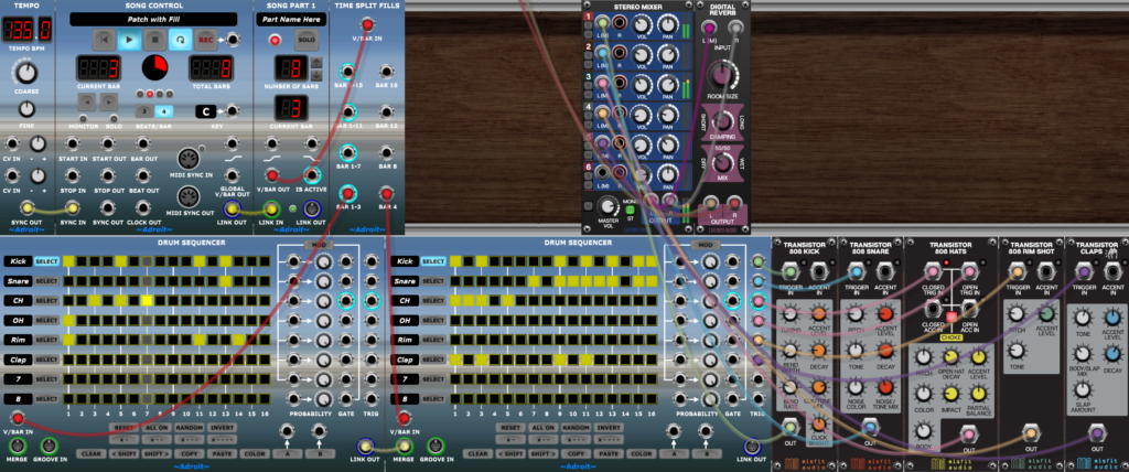
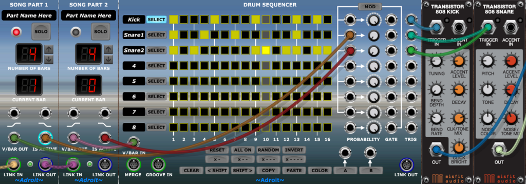
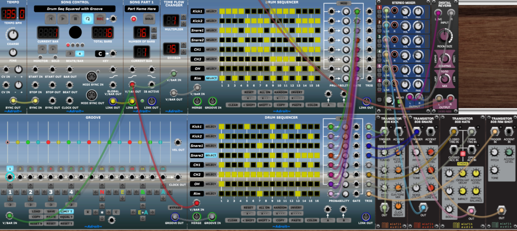
The setup below shows a Tempo module, a Song Control module and a Song Part module configured to create a basic Song Control Sequencer that feeds a V/Bar signal to the Drum Sequencer.
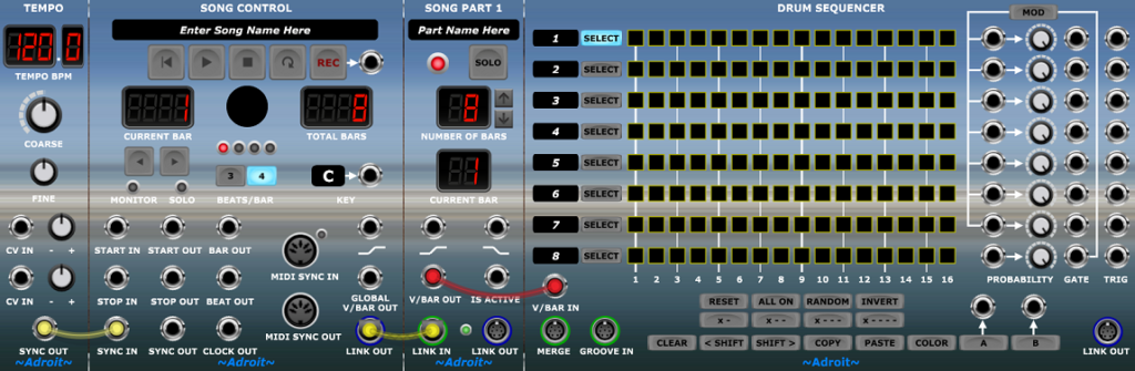
Pressing the Play button on the Song Control module will make the Drum Sequencer run for 8 bars and then stop. Engage the Loop button on the Song Control module to make the Drum Sequencer play continuously.
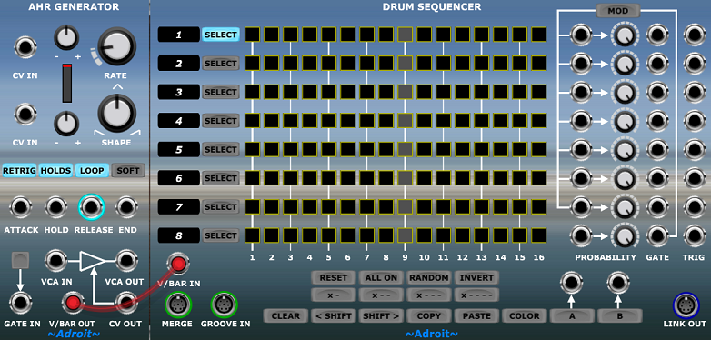
An alternative is to use the V/BAR OUT from an AHR Generator either to create a one off triggered sequence or a free-running repeating sequence if the generator’s LOOP button is engaged…
A simple first patch
Before we dive into technical detail and more advanced techniques, click on the Download button below and then open the downloaded file to launch Voltage Modular with a simple first patch.
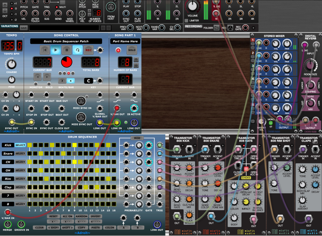
Click on the Song Control module’s play button. You should hear a simple one bar drum pattern looping. It’s using the default settings of the Misfit Audio drum modules so you might like to tweak their controls a little to get something slightly more interesting sounding but the main thing is to experiment with the controls on the Drum Sequencer to create your own patterns. You may initially want to increase Voltage Modular’s magnification to 150%. Hopefully, you will discover that basic operation is very straightforward and that your intuition works just fine.
If you hook up the trigger outputs from the first five tracks to a CV Watcher module (with its TIMEBASE knob turned fully anti-clockwise) then you’ll see something like this…
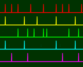
This is probably the kind of thing that you were expecting to see. So you may be wondering why does each track have a GATE output as well as a TRIGGER output?
Gates and triggers
The reason there are separate GATE and TRIGGER outputs is because the tracks have neither the TIE button nor the GATE TIME control that are available on Rhythm Sequencers yet you might still be interested in using the Drum Sequencer to drive envelope generators that can handle sustained notes. Also the subtle differences in behaviour between the two module types offers you a wider range of options.
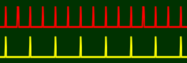
To understand how gates work in Drum Sequencer let’s program a simple pattern into a track and look at the gate and trigger signals from this single track using CV Watcher.

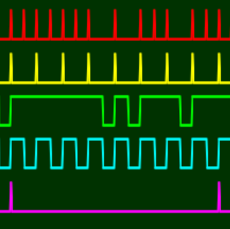
In the image below the red trace is taken from the BAR OUT socket of the Song Control module and shows the start of each bar.
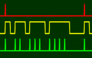
Notice how the GATE (yellow trace) stays high for one, then two, then three, then four steps; while the TRIGGER (green trace) outputs a pulse for each step that the gate is high.
So the GATE output behaves like a Rhythm Sequencer when the TIE button is engaged and GATE TIME is set at maximum, white the TRIGGER output behaves like a Rhythm Sequencer with the TIE button disengaged and GATE TIME set at minimum.
Having both signal types available simultaneously can be useful in some circumstances.
The LSSP XL Workshop London Crime Theme demonstrates the use of gates as well as triggers.
Moving beyond a single bar pattern
A single bar pattern repeated over and over soon becomes boring. Fortunately it’s pretty easy to chain Drum Sequencers and use Time Splitting to create more interesting forms. One very common form in drum programming is an AAAB fill so let’s look at implementing this.
The left-hand Drum Sequencer plays three times and then the right-hand one plays once before the whole thing repeats.
A Time Split Fills module looks after the V/Bar sequencing. Other types of Time Splitter modules can be used to create different forms – eg AB can be achieved with Time Split 2, ABCD or ABAC with Time Split 4 and so on.
Notice how the two sequencers are connected via a single S-Poly cable from LINK OUT to MERGE. As with other Adroit sequencers the chaining can be extended indefinitely and the order doesn’t matter. What does matter though is that only one sequencer in a chain is active at a time but this is pretty easy to arrange because of how Time Splitting works. Also always take the trigger and gate signals from the last sequencer in the chain otherwise bits will be missing.
Probability and “Solid Beats”
Although the Drum Sequencer uses the same basic probability mechanism as found in the Rhythm Sequencer the fact that there are multiple tracks in a single module can be exploited in interesting ways.
A track’s PROBABILITY knob sets the probability of a gate/trigger firing. The default setting is 100%. The CV input socket to the left of the knob enables the probability to be voltage controlled. This voltage control can be applied synchronously so that individual steps can have different probabilities.

Note that it is possible to completely turn off a track’s output with a zero probability setting. Something to watch out for if a track appears not to be working is that the PROBABILITY is accidentally set at zero.
When a signal is connected to the CV input the knob controls the minimum probability (i.e. when the control voltage is at zero volts). So when the knob is set at maximum the control voltage has no effect.
As well as offering useful adjustment to a modulating signal this allows a gate to be used to override the probability set by the knob. When the CV input is 5 volts the probability will be 100% and the knob has no effect. When the CV input is 0 volts the probability will be set by the knob.
This might all sound a bit complicated but let’s look at an example of why this is so useful.
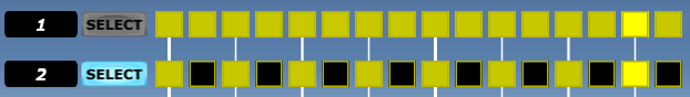
Let’s set the pattern of Track 1 to all on and the pattern of Track 2 to X- (in other words every other gate is on)…
When the PROBABILITY knobs of both tracks are set at the default of 100% the trigger outputs look like so…
If we turn down the PROBABILITY knob on Track 1 to 50% we end up with roughly half of the Track 1 triggers missing…
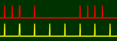
Which triggers are dropped from Track 1 is completely random (although on average about half of them will be dropped as the probability is set at 50%).
But if we patch the GATE output of Track 2 to the PROBABILITY CV input of Track 1 like so…
…then the probability of Track 1 is dynamically adjusted so that it’s 100% whenever the gate of Track 2 is high.
So Track 2 acts as a sort of “solid beat” control mechanism and only those steps in Track 1 where there isn’t a “solid beat” can be randomly removed.
Note that Track 1 will only ever produce a gate/trigger for a step if its own gate button for that step is on, it’s just that in this simple example they are all on. In practice any pattern can be used for either the controlled or controlling track.
This is a really useful technique that enables probability to be tightly controlled and made much more musically useful than mere randomness as you can dictate exactly which steps are random and which steps are fixed.
You can use this technique with multiple Rhythm Sequencers too but it takes up more space and is less elegant as the various controls are spread out instead of being in a nice neat vertical arrangement.
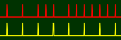
We’ve only been looking at the TRIGGER outputs in the CV Watcher traces above but the image below shows the GATE activity too…
Feeding gate signals to the PROBABILITY CV inputs is just one of many possibilities. You could use continuously variable signals from things like LFOs. One useful technique is to use the fade signals from Song Control or Song Part modules to make probability change slowly over the duration of a song or a section of a song.
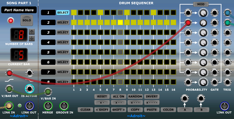
In the example shown above the probability of Track 2 producing a gate/trigger gradually changes from 0% to 100% as Song Part 1 progresses.
Normalled routing of probability modulation
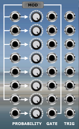
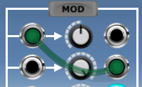
If you want to use the “solid beat” mechanism then any track’s GATE output can be patched to any other track’s PROBABILITY CV input but in most circumstances just one solid beat control track is sufficient. Therefore, there’s some built-in wiring that uses Track 8 for this purpose when the MOD button is engaged.

This sends Track 8’s GATE output to Track 1 to 7’s PROBABILITY CV inputs. These connections are normalled though, so you can override them by patching a lead to any of the input sockets. Also remember that any track whose PROBABILITY knob is set at 100% will ignore the CV input whether it’s via its own socket or via the normalled connection.
One of the uses for the A and B buttons at the bottom of the module is to break a normalled connection. The red cable in the image below disconnects Track 2’s connection to Track 8’s GATE enabling Track 2’s probability to be set independently by its knob.
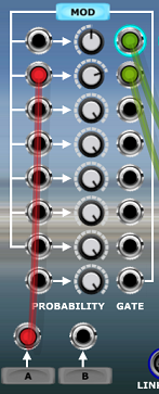
Because the A button is disengaged it’s feeding 0 volts to Track 2’s PROBABILITY CV input, meanwhile Track 1 and Track 3 to 7 are still receiving probability modulation from Track 8’s GATE output (because the MOD button is engaged). although in the example above this will have no actual effect on Tracks 3 through 7 because their PROBABILITY knobs are set at 100%.
Enabling the A button would send 5 volts to Track 2’s CV input so it would then ignore the knob setting and behave as if it was set at 100%.
Returning to the idea of using a solid beat control track to switch the probability of one or more other tracks on and off on a step by step basis, note that there is nothing special about a controlling track (apart from the handy default wiring provided for Track 8). So you are free to use a controlling track’s outputs as normal if you like.
For the sake of discussion let’s say we are using the Track 8 default wiring and the MOD button is engaged. Then any track from Track 1 to Track 7 that doesn’t have anything plugged into its PROBABILITY CV input and has its PROBABILITY knob set to something less than 100% will have its probability modulated by the solid beat pattern in Track 8.
But Track 8 also has its own probability control. So by setting its PROBABILITY knob to below 100% we can reduce the probability of Track 8’s GATE going high and therefore whether or not a beat is considered a solid one. In other words we can adjust the probability of a probability.
So if Track 8’s PROBABILITY knob is set at say 75% then there’s a 75% chance of any of the steps with a gate button on in its pattern producing a solid beat that modifies the behaviour of another track’s probability.
The best way to understand how all this works is to experiment. It soon becomes pretty obvious what’s going on and you can always patch up a CV Watcher module so that you can see as well as hear what’s happening.
A technical note (skip this if you aren’t curious about subtle limitations of voltage control of probability)…
Getting one’s head around semi-probable solid beats is difficult enough, but in theory it ought to be possible to use say Track 7’s GATE output to synchronously control the probability setting of Track 8 so that one could program some particular beats to always be solid while some were “less solid”. But unfortunately getting synchronous probability to work at the level of semi-probable solid beats has been technically challenging enough so for the moment at least controlling the probability of a probability of a probability doesn’t work reliably so the best you can achieve is using the solid beat controlling track’s PROBABILITY knob to make solid beats randomly less solid.
The technical reason behind these minor limitations is that for synchronous voltage control of probability to work the control voltage needs to be known at the point in time when the decision to fire or not is taken. But because of race conditions and propagation delays the controlling voltage is not determined until very slightly later. So when a track has a voltage controlled element in its probability (either directly via its input socket or via normalization ) then that track is delayed by a tiny amount of time to enable the voltage to become settled.
But if the source of that voltage control is itself subject to voltage control of its own probability then that needs to have a slight delay added too. So we end up with a complex cascade of tiny delays being required and for the moment at least the cost/benefit of such complex implementation is not deemed sensible.
Using voltage control of probability to implement muting
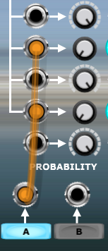
Another use for the A and B buttons is to implement mute groups. Let’s say you want to be able to mute and un-mute Tracks 5 and 7 with the push of a button. Simply patch the output from the A button to the PROBABILITY CV inputs of Track 5 and 7 and set their PROBABILITY knobs to 0%. Then they will only output triggers/gates when the A button is engaged.
Note that this muting only affects the module’s own signals, any signals passing through a chain via the MERGE connection are unaffected. Although because there’s nothing special about the A and B buttons (they are simply switches that output 0 volts or 5 volts to their socket) you can wire up an A or B button of one Drum Sequencer to another Drum Sequencer to achieve more widespread muting.
Using the PROBABILITY CV inputs to control muting can be useful in other contexts. For example perhaps we want one track to only be active when a particular section of a song is playing. Simply patch the IS ACTIVE output from the relevant Song Part module to the track’s PROBABILITY CV input and turn down the track’s PROBABILITY knob to 0%.
Maybe we want a different snare pattern depending on which section of a song is playing but everything else remains the same. Rather than use another Drum Sequencer we can simply switch between two tracks as demonstrated below.
If there are lots of parts to a song and you want to switch between tracks in say the bridge of a song then the wiring involved using this technique can get pretty messy (especially if you want to switch more than two tracks at a time). One option is to use Voltage Modular’s bus system but another is to use a logic invertor. There’s one in the V/Bar Utility module.
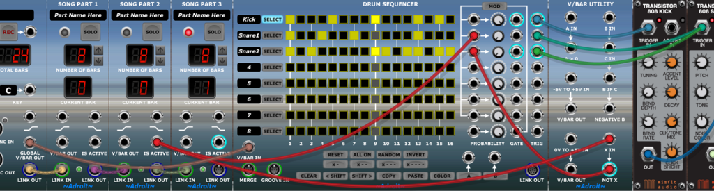
In the example above the IS ACTIVE signal from Song Part 2 sets the probability of Track 2 to 100% when Song Part 2 is playing. The same signal is sent to the X IN socket of the invertor in the V/Bar Utility module and the NOT X output is used to control Track 3. So Track 3 only becomes active when Song Part 2 is not active.
Also note that rather than wiring all three V/BAR OUT sockets from the three Song Part modules to the V/BAR IN socket of the Drum Sequencer, a single cable is used to connect the GLOBAL V/BAR OUT signal to the Drum Sequencer as in this instance the Drum Sequencer plays continuously.
Using a Drum Sequencer to control the muting of tracks in another Drum Sequencer
Extending the idea of muting control, it is relatively easy to use the gate outputs of one Drum Sequencer to control which tracks are active in another Drum Sequencer.
Obviously this is of little use when both sequencers are running at the same speed but we can use the Time Flow Changer module to slow down the controlling sequencer so that it only changes step once per bar. Then one can control which tracks of the controlled sequencer are active for each bar in a pattern up to 16 bars long.
This is quite a powerful technique so here’s a ready built patch for you to explore…
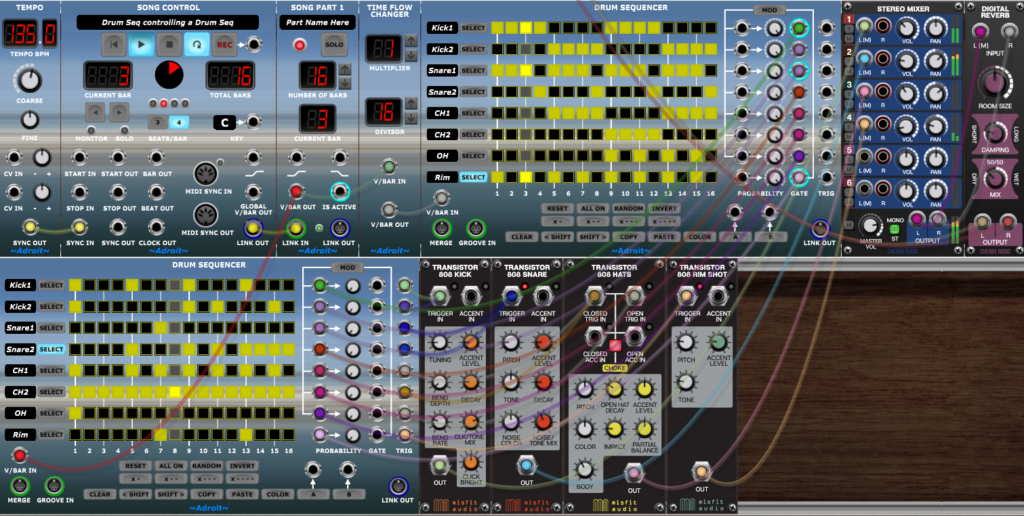
It’s essentially just the basic introductory patch we began with but the Claps module has been dropped and a Time Flow Changer and another Drum Sequencer have been added.
The Time Flow Changer is set to slow down time by a factor of 16, which makes the Drum Sequencer at the top change step once per bar instead of 16 times per bar. Each gate output from the slow top sequencer is patched to the PROBABILITY CV input of the corresponding track in the Drum Sequencer at the bottom and all the PROBABILITY knobs in the lower sequencer are turned down to 0% so that all tracks only produce gates/triggers when their PROBABILITY CV input is non-zero.
When using this technique it’s important that a controlled track’s PROBABILITY knob is set at exactly 0%. If it’s say 1% then the knob might look like it’s at 0% but you’ll end up with mysterious out of place gate/triggers popping up once in a while.
This idea can be indefinitely expanded by using time splitting, chaining and multiple parallel Drum Sequencers to create far more complex patterns but it’s best to be absolutely familiar with how this basic patch works before venturing into such territory.
Three beats per bar operation
To easily support 3/4 and related time signatures Song Control provides an option to switch from 4 beats per bar to 3 beats per bar.

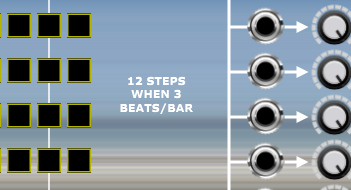
When Song Control is set at 3 beats per bar then Drum Sequencer modules switch from 16 steps to 12 steps because 16 is not divisible by 3.
It’s more complicated when the Groove module is used but this will be covered later. For now just assume that there are 4 steps per beat whether in 4 beats per bar or 3 beats per bar mode (4 * 4 = 16, 3 * 4 = 12).
As you may rarely use 3 beats per bar mode a helpful message appears to let you know why some steps are missing.
Groove control
As with the Rhythm Sequencer, the Drum Sequencer has a GROOVE IN socket that enables a groove signal to be received from a Groove module. But unlike the Rhythm Sequencer the Drum Sequencer does not handle velocities so only the timing elements of a groove signal are used. However, the Groove module has a VEL OUT socket that outputs the velocity of the current step so with a little bit of care we can add velocity control.
Retro-fitting a groove to an existing song is pretty tricky. Generally it’s best to add a groove in the very earliest stages of composition so that the everything fits together properly. But for the sake of explanation let’s go ahead anyway and add a groove module to Drum-Seq-Squared patch we’ve just been looking at.
The wiring is simple, just a V/Bar connection to the V/BAR IN socket of the added module and a single S-Poly connection from the GROOVE OUT socket to the GROOVE IN socket of the lower Drum Sequencer.
Initially, this patch will sound exactly the same as the previous patch because the Groove module is in its default neutral state.
As described above it’s difficult retro-fitting a groove to existing material so we’ll just make a rather crude change for the purpose of illustration.
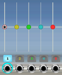
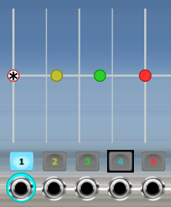
Locate the -3- buttons in the bottom left of the Groove module underneath the 1, 2, 3, 4 labels and click on each one.

This turns each group of four steps for each of the four beats into groups of three.
So the straight 16 step pattern turns into a 12 step pattern that has the sound of heavy swing. It’s a slightly cheesy sound but works.
The change results in the “collapse” of steps 4, 8, 12 and 16 and a timing redistribution in the remaining steps. See the Groove documentation for more information on the concept of “step collapse”.
As well as the obvious audible difference the impact of the step collapse can be seen in the Drum Sequencer’s appearance.
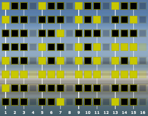
Note that the collapsed steps are semi-transparent as an indication that are being skipped over.
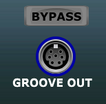
The Groove module has a handy BYPASS feature that enables you to compare groove and non-groove behaviour at the press of a button.
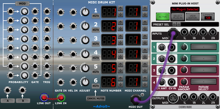
Linking to the MIDI Drum Kit module
The MIDI Drum Kit module has a LINK IN S-Poly socket that can be connected to the Drum Sequencer’s LINK OUT socket. This connection provides exactly the same functionality as patching six cables from the TRIG outputs of Track 1 through 6 to the GATE IN sockets of Channel 1 to 6 of the MIDI Drum Kit. It’s just a convenient feature that saves you having to waste time patching.
Availability
The Drum Sequencer is part of the LSSP XL bundle.